
Vessel tank, tank container, horizontal-type storage tank, highway tanker, and railway tanker

A container tank and inner container technology, which is applied in the field of storage and transportation equipment, can solve problems such as failure of the support part of the low temperature container tank body, and achieve the effects of enhancing stability, improving stress distribution, and solving failure risks.

Pending Publication Date: 2018-10-02
CRRC YANGTZE CO LTD
View PDF0 Cites 4 Cited by
  • Summary
  • Abstract
  • Description
  • Claims
  • Application Information

AI Technical Summary

Problems solved by technology

[0006] The application provides container tanks, tank containers, horizontal storage tanks, road tank cars, and railway tank cars, which solves or partially solves the technical problem that the support parts of low-temperature container tanks in the prior art have the risk of failure

Method used


Image

  • Vessel tank, tank container, horizontal-type storage tank, highway tanker, and railway tanker
  • Vessel tank, tank container, horizontal-type storage tank, highway tanker, and railway tanker
  • Vessel tank, tank container, horizontal-type storage tank, highway tanker, and railway tanker

Examples


Embodiment 1

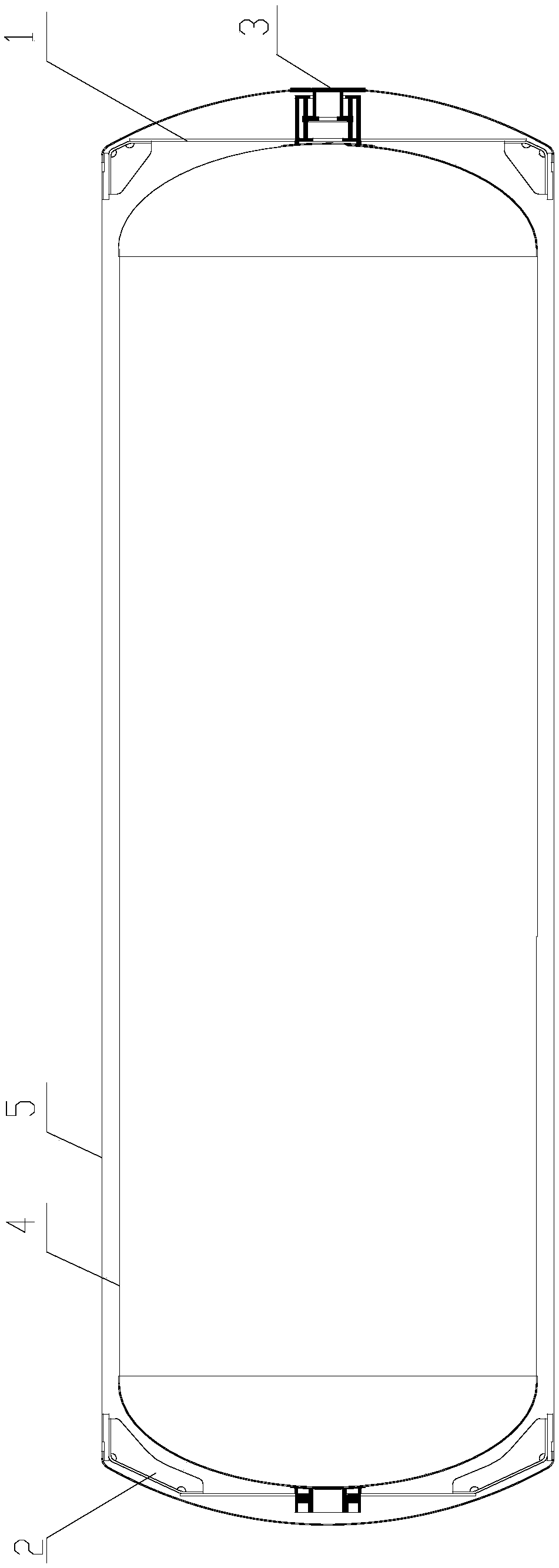
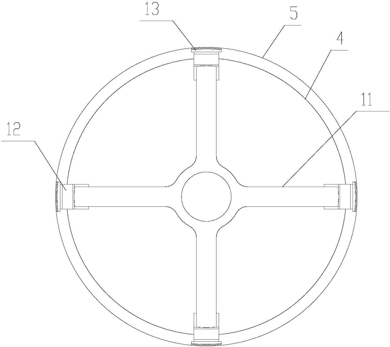
[0059] See attached figure 1 , the present embodiment provides a container body, including an inner container 4 and an outer shell 5, and the inner container 4 and the outer shell 5 are arranged coaxially; the container body also includes: a fixed end sling device 1 and a sliding end sling device 2 ,in:

[0060] The fixed-end sling device 1 is arranged between the head of one end of the outer shell 5 and the head of the inner container 4 corresponding to the end of the outer shell 5, and the fixed-end sling device 1 is connected to the head of the inner container 4 to transfer a part of the weight of the inner container 4 on the shell 5; the sliding end sling device 2 is arranged between the head of the other end of the shell 5 and the head of the inner container 4 corresponding to the end of the outer shell 5, the sliding end sling device 2 is connected to the head of the inner container 4, and the contents The remaining weight of the device 4 is transferred to the shell 5. ...

Embodiment 2

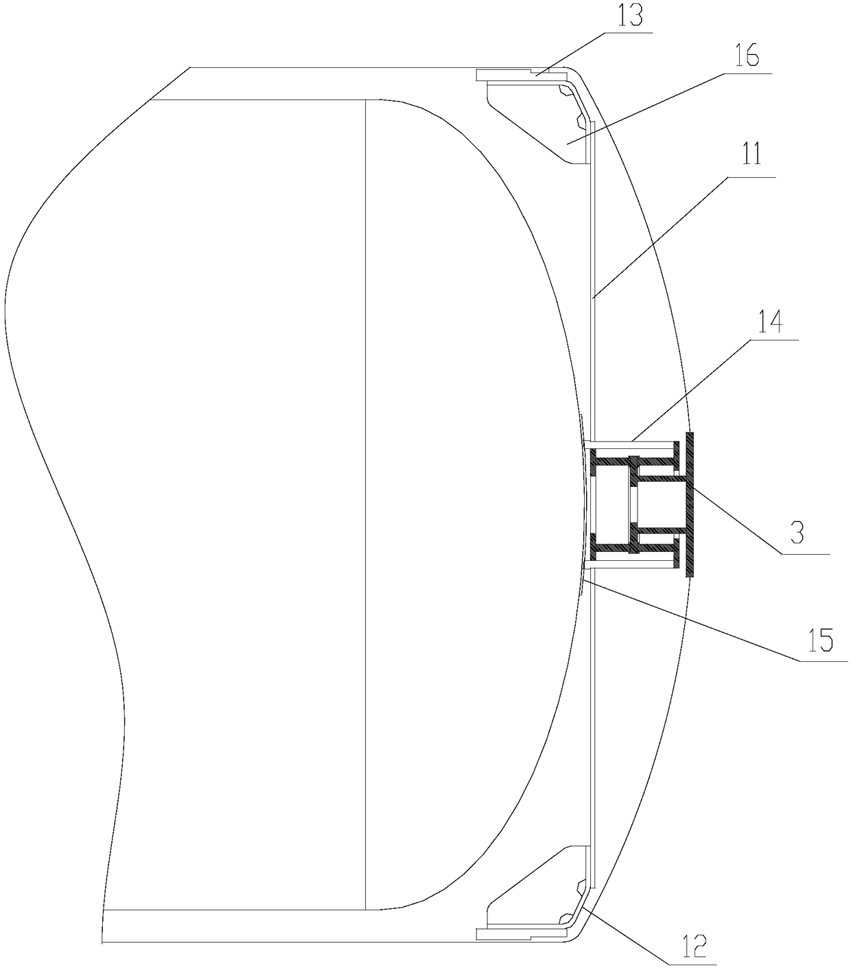
[0079] See attached figure 1, the container body provided in this embodiment not only includes the inner container 4, the outer shell 5, the fixed end sling device 1 and the sliding end sling device 2 in the first embodiment, but also includes a longitudinal displacement restraining device 3, which is arranged close to the sliding end sling device 2 , see attached Figure 10 and 11 , the longitudinal displacement restraint device 3 includes: a blocking plate 31, a connecting pipe 32, a mounting plate 33, a first limiting plate 34, a second limiting plate 35, a first glass steel pipe 36 and a second glass steel pipe 37, wherein:

[0080] The blocking plate 31 is fixedly connected with the right end head of the shell 5; one end of the connecting pipe 32 is fixedly connected with the blocking plate 31, and the other end is fixedly connected with the mounting plate 33; one side of the mounting plate 33 is provided with a first annular groove 331, and the other The side is provid...


PUM


Abstract

The invention relates to a vessel tank, a tank container, a horizontal-type storage tank, a highway tanker, and a railway tanker. The vessel tank comprises an inner vessel, a shell, a fixed end slingdevice and a sliding end sling device. The fixed end sling device comprises a first sling, first sling connecting plates and first tubular supports; the first sling connecting plates are fixed to theends of the first sling correspondingly; the first sling connecting plates are fixedly connected with the shell; and one end of each first tubular support is fixedly connected with a right end socketof the inner vessel. The sliding end sling device comprises a second sling, second sling connecting plates and second tubular supports; the second sling connecting plates are fixed to the ends of thesecond sling correspondingly; the second sling connecting plates are fixedly connected with the shell; and one end of each second tubular support is fixedly connected with a left end socket of the inner vessel. According to the vessel tank, stress distribution of the inner vessel and shell cylinder positions is effectively improved, and the stability of a tank structure is enhanced.

Description

technical field [0001] The invention relates to the technical field of storage and transportation equipment, in particular to a container body and a tank container, a horizontal storage tank, a road tank car, and a railway tank car. Background technique [0002] Cryogenic liquid storage and transportation equipment is a kind of container equipment composed of low-temperature tanks and supporting devices, which is specially used for storing and transporting deep-cold liquids. The internal temperature of the container is very low during operation, which can reach below -160°C . The tank body is the core device in cryogenic liquid storage and transportation equipment, and usually consists of an inner tank, an outer shell, and a connection and fixing device between the inner tank and the outer shell. Among them, the inner tank is used to store deep-cold liquid, and the shell and the inner tank are combined to form a closed interlayer. After the interlayer is evacuated to form a...

Claims


Application Information

Patent Timeline
IPC IPC(8): B65D90/02B65D88/12B60P3/22B61D5/06F17C1/12
CPCF17C1/12B61D5/06B65D88/128B65D90/02B60P3/2215
Inventor 黄政贤何远新吕长乐胡海滨刘凤伟杨清义熊珍艳卢海霍海波李永莉费锦华黄圣杨帅
Owner CRRC YANGTZE CO LTD
Learn More