Double check diaphragm check valve

A check valve, diaphragm technology, applied in the direction of lift valve, valve details, control valve, etc., can solve the problem of oil return phenomenon, small contact area, etc., to achieve good check effect, increase contact area, and easy to clean. Effect

Pending Publication Date: 2018-10-02
ANHUI LIWEI PRECISION MACHINERY
View PDF0 Cites 1 Cited by
  • Summary
  • Abstract
  • Description
  • Claims
  • Application Information

AI Technical Summary

Problems solved by technology

[0004] The invention aims to overcome the problem that the contact area between the diaphragm assembly and the inside of the valve chamber is small, and oil return is likely to occur when the oil pressure is too high. The purpose of the present invention is to provide a double check diaphragm check valve

Method used


Image

  • Double check diaphragm check valve
  • Double check diaphragm check valve
  • Double check diaphragm check valve

Examples


Embodiment 1

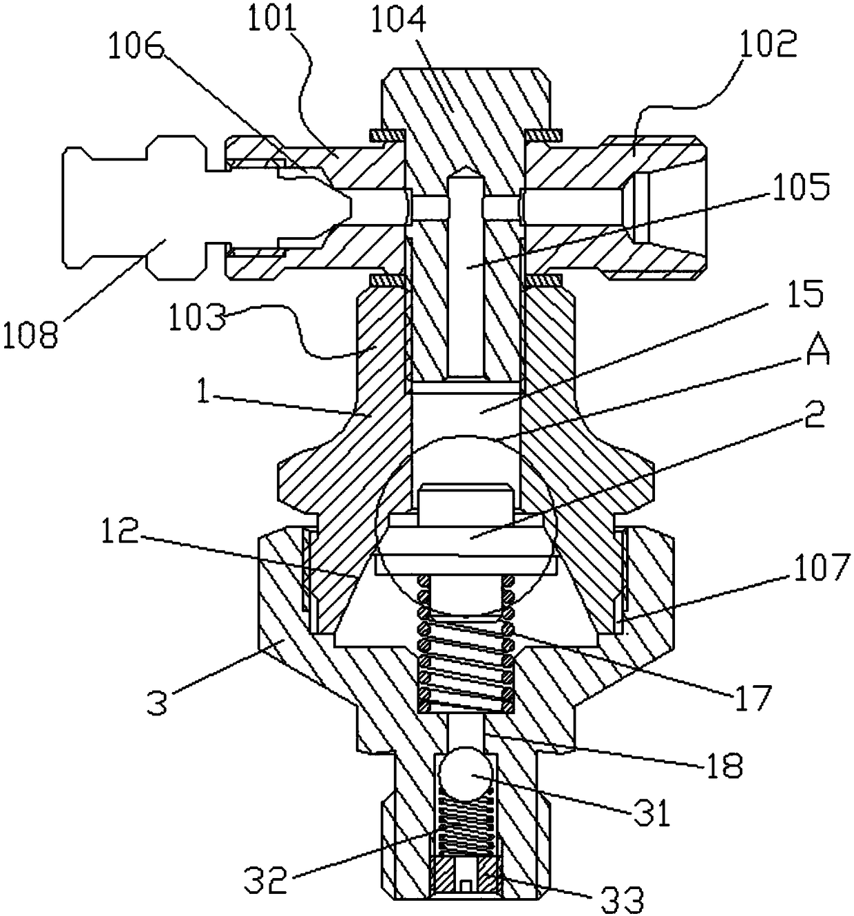
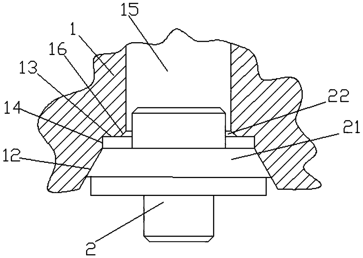
[0028] exist figure 1 on the basis of image 3 Shown; a double check diaphragm check valve, including a valve body 1 with a funnel-shaped mouth 12 inside the lower end, a diaphragm assembly 2 installed inside the mouth 12, and a valve body installed at the lower end of the valve body 1 The lower end cover 3, the central axis of the bucket mouth 12 coincides with the central axis of the valve body 1, the bottom of the bucket mouth 12 is provided with a stepped surface 13, the stepped surface 13 is perpendicular to the central axis of the valve body 1, and the stepped surface 13 is connected to the side of the bucket mouth 12 A cylindrical surface 14 is arranged between them. The upper end structure of the diaphragm 21 of the diaphragm assembly 2 is a cylinder, and the lower end structure is a circular platform. The cylindrical structure part of the diaphragm 21 is located on the cylindrical surface 14, and the circular platform part of the diaphragm 21 is located in the bucket ...

Embodiment 2

[0036] exist figure 1 on the basis of image 3 Shown; a double check diaphragm check valve, including a valve body 1 with a funnel-shaped mouth 12 inside the lower end, a diaphragm assembly 2 installed inside the mouth 12, and a valve body installed at the lower end of the valve body 1 The lower end cover 3, the central axis of the bucket mouth 12 coincides with the central axis of the valve body 1, the bottom of the bucket mouth 12 is provided with a stepped surface 13, the stepped surface 13 is perpendicular to the central axis of the valve body 1, and the stepped surface 13 is connected to the side of the bucket mouth 12 A cylindrical surface 14 is arranged between them. The upper end structure of the diaphragm 21 of the diaphragm assembly 2 is a cylinder, and the lower end structure is a circular platform. The cylindrical structure part of the diaphragm 21 is located on the cylindrical surface 14, and the circular platform part of the diaphragm 21 is located in the bucket ...


PUM


Abstract

A double check diaphragm check valve relates to the field of check valves, and comprises a valve body having a funnel-shaped mouth at the lower inner end, a diaphragm assembly mounted inside the funnel-shaped mouth, and a lower end cover mounted at the lower end of the valve body, wherein a central axis of the funnel-shaped mouth coincides with a central axis of the valve body; a step surface is arranged at the bottom of the funnel-shaped mouth; the step surface is perpendicular to the central axis of the valve body; a column-shaped surface is connected between the step surface and a side surface of the funnel-shaped mouth; the upper end structure of the diaphragm assembly is a cylinder; the lower end structure of the diaphragm assembly is a circular truncated cone; the cylindrical structure part of the diaphragm is arranged on a cylindrical surface; and the circular truncated cone of the diaphragm is arranged on the inclined surface of the bucket opening. Due to the cylindrical surface at the upper end of the diaphragm and the step surface at the inner end of the funnel-shaped mouth, the contact area between the diaphragm and a valve cavity in the funnel-shaped mouth is enlarged,so that the upper end of the diaphragm and the valve cavity define a one-end plunger space, to avoid oil return.

Description

technical field [0001] The invention relates to the field of check valves, in particular to a double check diaphragm check valve. Background technique [0002] Check valve refers to a valve that automatically opens and closes the valve disc by relying on the flow of oil itself to prevent oil from flowing back. It is also called check valve, one-way valve, reverse flow valve, and back pressure valve. The check valve is a kind of automatic valve, its main function is to prevent the backflow of oil, prevent the reverse of the pump and drive motor, and discharge the oil in the container. [0003] Traditional check valves mostly use ball valve checks. For some pipelines with high oil pressure, the check effect is not good and oil return is easy to occur. For other diaphragm check valves, because the diaphragm and the inside of the valve cavity are only The side of the bucket is connected, resulting in a small contact surface between the diaphragm and the valve cavity. When the o...

Claims


Application Information

Patent Timeline
Patent Type & Authority Applications(China)
IPC IPC(8): F16K15/06F16K15/04F16K1/42F16K47/04F16K27/02
CPCF16K15/066F16K1/42F16K15/044F16K27/0209F16K47/04
Inventor 邓志威邓加先胡知富
Owner ANHUI LIWEI PRECISION MACHINERY
Why Eureka
Try Eureka