
Driving method of liquid crystal display panel

A liquid crystal display panel and driving method technology, applied to static indicators, instruments, etc., can solve the problems of high cost, difficulty in making breakthroughs in afterimage improvement, and affecting image display, etc., to achieve low cost and improve panel residual Shadow, simple effect

Active Publication Date: 2018-10-02
KUSN INFOVISION OPTOELECTRONICS
View PDF6 Cites 1 Cited by
  • Summary
  • Abstract
  • Description
  • Claims
  • Application Information

AI Technical Summary

Problems solved by technology

However, it is currently impossible to find a liquid crystal that does not contain ionic impurities, nor can it guarantee that ionic impurities will not be brought in during the manufacturing process. is also extremely expensive
Therefore, the usual way to improve panel afterimage is to change the common electrode from DC drive mode (DC Vcom) to AC drive mode (AC Vcom). However, if the AC drive voltage is too high, it will affect the normal deflection of the liquid crystal and affect the screen display. If it is too small, the effect of improving panel afterimage is not obvious

Method used


Image

  • Driving method of liquid crystal display panel
  • Driving method of liquid crystal display panel
  • Driving method of liquid crystal display panel

Examples


Embodiment Construction

[0025] In order to further explain the technical means and effects that the present invention adopts to achieve the intended purpose of the invention, the specific implementation, structure, characteristics and details of the driving method of the liquid crystal display panel proposed according to the present invention will be described below in conjunction with the accompanying drawings and preferred embodiments. Its efficacy is described in detail as follows:

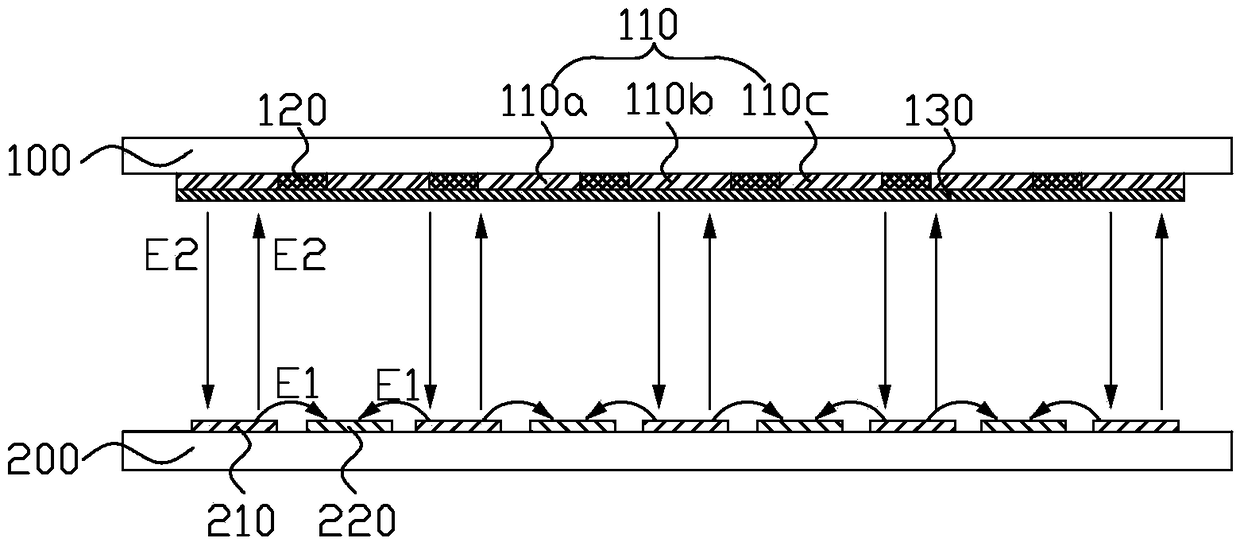
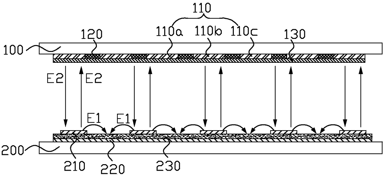
[0026] Such as figure 1 with image 3 As shown, the driving method of the liquid crystal display panel provided by the embodiment of the present invention, wherein the liquid crystal display panel includes a first substrate 100, a second substrate 200, and liquid crystal molecules interposed between the first substrate 100 and the second substrate 200 (Fig. not shown), wherein the first substrate 100 is a color filter substrate, and the second substrate 200 is a thin film transistor array substrate (hereinafter refer...


PUM


Abstract

The invention discloses a driving method of a liquid crystal display panel. The liquid crystal display panel comprises a first substrate, a second substrate and liquid crystal molecules between the first substrate and the second substrate, wherein the first substrate is provided with an auxiliary electrode, and the second substrate is provided with a pixel electrode and a common electrode. The driving method comprises the steps of applying a first voltage signal to the auxiliary electrode, and applying a second voltage signal to the common electrode. In a display time period, both the first voltage signal and the second voltage signal are direct current voltage. In a non-display time period, at least one of the first voltage signal and the second voltage signal is alternating current voltage. The auxiliary electrode and the common electrode are enabled to have a voltage difference therebetween and generate a vertical electric field with alternating current changes in the non-display time period. The driving method can drive impure ions to ceaselessly oscillate up and down in a liquid crystal box, thereby preventing the impure ions from being attached to the surfaces of two substrates to result in ghosts, and achieving an effect of improving the panel ghosts. The driving method is simple in implementation and low in cost.

Description

technical field [0001] The invention relates to the technical field of liquid crystal display, in particular to a driving method of a liquid crystal display panel. Background technique [0002] Liquid crystal display (LCD) has the advantages of good image quality, small size, light weight, low driving voltage, low power consumption, no radiation and relatively low manufacturing cost, and occupies a dominant position in the field of flat panel display. The liquid crystal display panel includes an opposite color filter substrate (color filter, CF) and a thin film transistor array substrate (TFTarray), and a liquid crystal layer (LC layer) sandwiched between them. [0003] Due to the limitation of structure and process technology, the liquid crystal display panel has the problem of image sticking (IS). Afterimage is a phenomenon in which the same still picture is displayed for a long time, positive and negative ions will easily attach to the surface of the pixel electrode and ...

Claims


Application Information

Patent Timeline
Patent Type & Authority Applications(China)
IPC IPC(8): G09G3/36
CPCG09G3/3648
Inventor 钟德镇林沛炀赵麟瑄王新刚王博王旭宏
Owner KUSN INFOVISION OPTOELECTRONICS
Learn More