Explosion-proof electric cabinet with dehumidification function

A technology of electrical cabinets and functions, applied in the field of electrical cabinets, can solve the problems of no explosion-proof and heat dissipation, no dehumidification function, no ability to prevent rainwater and dust from entering the inside of the electrical cabinet, etc., and achieve the effect of reducing moisture penetration and safe use.

Inactive Publication Date: 2018-10-02
HEFEI DEJIE ENERGY CONSERVATION & ENVIRONMENTAL PROTECTION TECH CO LTD
View PDF0 Cites 4 Cited by
  • Summary
  • Abstract
  • Description
  • Claims
  • Application Information

AI Technical Summary

Problems solved by technology

[0003] The purpose of the present invention is to provide an explosion-proof electrical cabinet with dehumidification function to solve the problem that the general electrical cabinets on the market proposed in the abo

Method used


Image

  • Explosion-proof electric cabinet with dehumidification function
  • Explosion-proof electric cabinet with dehumidification function
  • Explosion-proof electric cabinet with dehumidification function

Examples


Embodiment 1

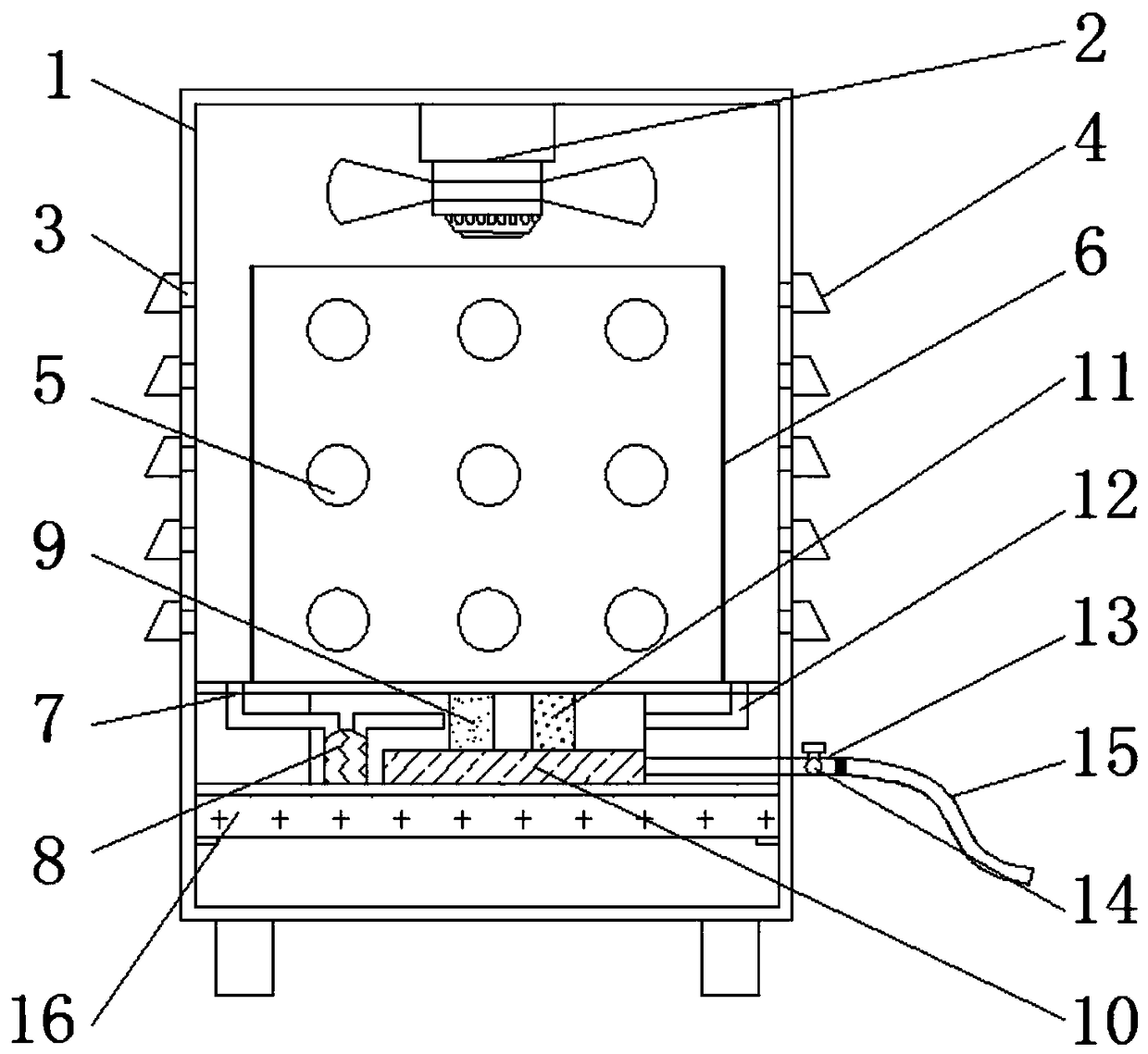
[0022] Example 1, such as figure 1 Cooling hole 3 and dustproof cover 4 are arranged in one-to-one correspondence, and the longitudinal section shape of dustproof cover 4 is trapezoidal, makes rainwater fall on the dustproof cover 4 and falls by inclined-plane after, does not contact with cooling hole 3, can avoid rainwater and Dust enters the interior of the device, and the bottom of the dust cover 4 communicates with the outside world, so that the internal air can circulate with the outside world through the cooling holes 3 and the lower end of the dust cover 4 to achieve the purpose of heat dissipation;

Embodiment 2

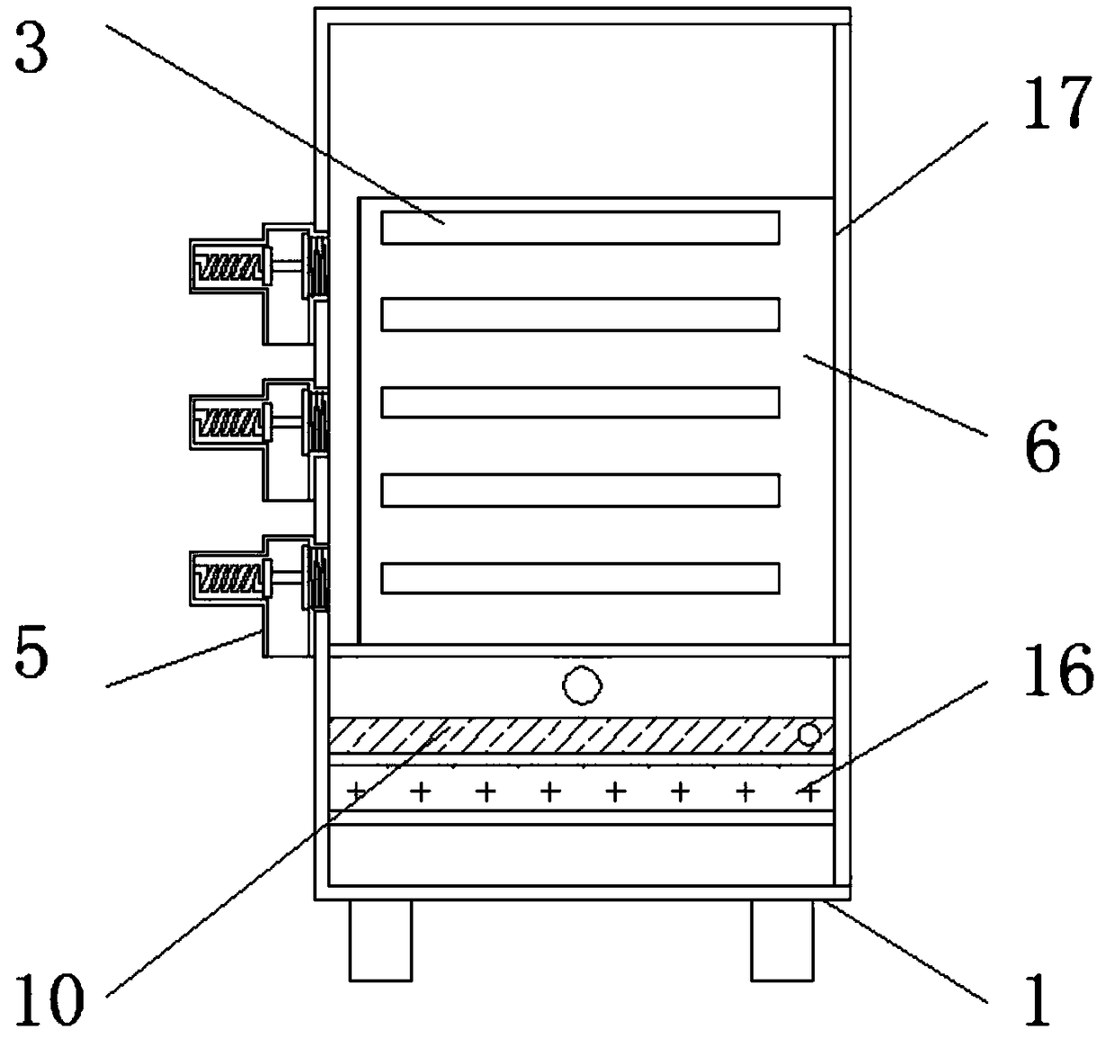
[0023] Example 2, such as Figure 4 The pressure sensing block 504 forms a telescopic structure on the pressure relief block frame body 501, and the diameter of the right side of the pressure sensing block 504 is larger than the inner diameter of the air inlet 505. When the internal pressure value is normal, the pressure sensing block 504 and the air inlet 505 Contact and block the air inlet 505. When the internal pressure is large, push the pressure-sensitive block 504 to compress to the right, so that the air inlet 505 is connected with the air outlet 502, so that the internal high-pressure gas flows out quickly, achieving the purpose of pressure relief and explosion protection.

[0024] Working principle: When using the explosion-proof electrical cabinet with dehumidification function, firstly, the fan 2 rotates to drive the air flow inside the device, so that the internal hot air flows to the outside of the device through the cooling holes 3, and the cold air is exchanged i...


PUM


Abstract

The invention discloses an explosion-proof electric cabinet with a dehumidification function. The explosion-proof electric cabinet comprises an electric cabinet frame body, pressure relief block bodies and an air inlet pipe, wherein a fan is arranged on the upper surface of the inner side of the electric cabinet frame body; heat emission holes are reserved in the left side and the right side of the electric cabinet frame body; a dustproof cover is arranged at the outer side of each heat emission hole; the pressure relief block bodies are located on the rear side surface of the electric cabinetframe body; a protection net is arranged at the inner side of the electric cabinet frame body; the air inlet pipe is located at the lower left corner of the protection net and connected with a compressor; a condenser is arranged at the right side of the air inlet pipe; a water tank is arranged at the lower part of the condenser; an evaporator is arranged at the right side of the condenser; and anair outlet pipe is arranged at the right side of the evaporator. The explosion-proof electric cabinet with the dehumidification function is capable of removing moisture in a device, preventing the moisture at the lower part from entering the inside of the device, preventing explosion, dissipating heat and preventing rainwater and dust from entering the inside of the device.

Description

technical field [0001] The invention relates to the related technical field of electrical cabinets, in particular to an explosion-proof electrical cabinet with a dehumidification function. Background technique [0002] The electrical cabinet is made of steel to protect the normal operation of the components. The electrical cabinet is widely used in the chemical industry, environmental protection industry, power system, metallurgical system, industry, nuclear power industry, fire safety monitoring and transportation industry, etc. However, the general electrical cabinets on the market do not have dehumidification function, and cannot prevent explosion and heat dissipation, and cannot prevent rainwater and dust from entering the inside of the electrical cabinet. Therefore, we propose an explosion-proof electrical cabinet with dehumidification function to solve the above problems. The problem. Contents of the invention [0003] The purpose of the present invention is to prov...

Claims


Application Information

Patent Timeline
IPC IPC(8): H05K7/20
CPCH05K7/20554H05K7/20663
Inventor 卢世军
Owner HEFEI DEJIE ENERGY CONSERVATION & ENVIRONMENTAL PROTECTION TECH CO LTD
Why Eureka
Try Eureka