Temperature sensor cutting device

A technology of temperature sensor and cutting device, which is applied in the field of temperature sensor cutting device, can solve the problems of different lengths, uneven cutting plane of CP wire, etc., and achieve the effect of neat cutting plane

Inactive Publication Date: 2018-10-09
刘浩荫
View PDF0 Cites 0 Cited by
  • Summary
  • Abstract
  • Description
  • Claims
  • Application Information

AI Technical Summary

Problems solved by technology

[0002] At present, the cutting device needs to be manually cut, and the

Method used


Image

  • Temperature sensor cutting device

Examples


Embodiment Construction

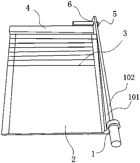
[0011] Such as figure 1 Shown, a kind of temperature sensor cutting device, it comprises cutting knife body 1 and cutting platform 2, and described cutting knife body 1 is fixedly arranged on cutting platform 2, and described cutting platform 2 is provided with scale scale layer 3, and described One end of the cutting platform 2 is provided with a boss 4 , and one end of the boss 4 is provided with a hinge device 5 , and the cutting knife body 1 is provided with a hinge hole 6 , and the hinge device 5 cooperates with the hinge hole 6 .

[0012] The width of the cutting platform 2 is 10-15cm.

[0013] The cutter body 1 is composed of a cutting blade 101 and a support frame 102, and the cutting blade 101 is made of stainless steel.

[0014] The width of the cutter body 1 is 5-8cm.

[0015] Before operation and during operation, take 5 pieces of semi-finished products to be trimmed at the end every hour, cut a few pieces, confirm whether the total length is 44-48mm, and the exp...


PUM

PropertyMeasurementUnit
Widthaaaaaaaaaa
Widthaaaaaaaaaa

Abstract

The invention relates to a temperature sensor cutting device. The temperature sensor cutting device comprises a cutting knife body and a cutting platform. The cutting knife body is fixedly arranged onthe cutting platform. The cutting platform is provided with a scale label layer. One end of the cutting platform is provided with a boss, and one end of the boss is provided with a hinge device. Thecutting knife body is provided with a hinge hole, and the hinge device coordinates with the hinge hole. After the cutting device is adopted, CP cutting is rapid, cutting planes are tidy and accurate,and CP lines are not curved.

Description

technical field [0001] The invention relates to a temperature sensor cutting device. Background technique [0002] At present, the cutting device needs to be cut manually, and the cutting plane of the CP line is not neat, resulting in different lengths. Contents of the invention [0003] In order to solve the above problems, the present invention provides a cutting device for temperature sensors that can easily cut redundant CP wires. [0004] The invention provides a temperature sensor cutting device, which includes a cutting knife body and a cutting platform, the cutting knife body is fixedly arranged on the cutting platform, a scale scale layer is provided on the cutting platform, and one end of the cutting platform is provided with A boss, a hinge device is provided at one end of the boss, a hinge hole is arranged on the cutting knife body, and the hinge device is matched with the hinge hole. [0005] Preferably, the width of the cutting platform is 10-15cm. [0006...

Claims


Application Information

Patent Timeline
IPC IPC(8): B21F11/00
CPCB21F11/00
Inventor 刘浩荫
Owner 刘浩荫
Why Eureka
Try Eureka