Precision blanking machine with features of high efficiency, cyclical impact and low stress

A technology of cyclic impact and cutting machine, which is applied in the direction of nibbling cutting devices, shearing machine accessories, shearing devices, etc., which can solve the problems of inability to adjust the size of the force arm, unstable crack propagation, and cutting efficiency. Low-level problems, to achieve the effect of improving the quality of the blanking section

Active Publication Date: 2018-10-09
CHINA UNIV OF PETROLEUM (EAST CHINA)
View PDF8 Cites 2 Cited by
  • Summary
  • Abstract
  • Description
  • Claims
  • Application Information

AI Technical Summary

Problems solved by technology

For low-stress blanking, in view of the important achievements in blanking efficiency and energy saving, there are still technical problems such as unstable crack growth, wear of high-speed rotating parts, and low blanking efficiency, and it is necessary to solve the only current constraints on large-scale applications. Therefore, it is proposed to adopt catastrophe theory and micro-crack theory to reveal the material change of the bar during the whole process of crack initiation, crack propagation and instantaneous fracture, and to establish the exact relationship between external force and crack length.
[0006] However, the existing low-stress blanking machine has certain limitations in the study of the relationship between external force and the crack initiation and propagation of the bar and in improving the blanking efficiency. Expansion and real-time changes lead to the inability to adjust the size of the force arm. At the same time, the existing low-stress vibrating blanking machine cannot conveniently change the force moment after the crack starts to improve the section quality of the bar, and the blanking efficiency is relatively low. , only one section of bar can be placed at a time

Method used


Image

  • Precision blanking machine with features of high efficiency, cyclical impact and low stress
  • Precision blanking machine with features of high efficiency, cyclical impact and low stress
  • Precision blanking machine with features of high efficiency, cyclical impact and low stress

Examples


Embodiment Construction

[0026] The technical solutions in the embodiments of the present invention will be clearly and completely described below in conjunction with the accompanying drawings in the embodiments of the present invention. Obviously, the described embodiments are only a part of the embodiments of the present invention, rather than all the embodiments. Based on the embodiments of the present invention, all other embodiments obtained by those of ordinary skill in the art without creative work shall fall within the protection scope of the present invention.

[0027] The following will be attached figure 1 ~attached Figure 7 The technical solutions of the present invention are described in detail with specific embodiments.

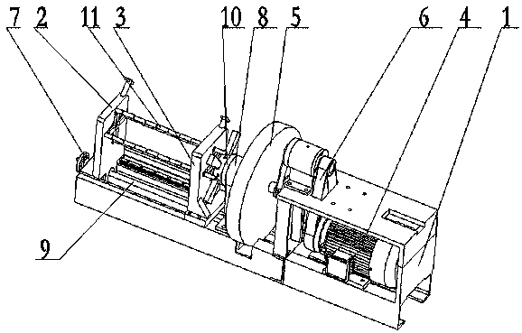
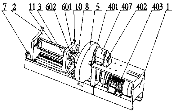
[0028] reference figure 1 , figure 2 , image 3 , Figure 4 with Figure 5 As shown, a high-efficiency cyclic impact and low-stress precision cutting machine according to an embodiment of the present invention includes a frame 1, a first clamping device movably installed o...


PUM


Abstract

The invention provides a precision blanking machine with the features of high efficiency, cyclical impact and low stress, and relates to the technical field of machining. The lower part of an impact block is provided with equidistant grooves matched with first spiral wire coils; in the working process of the precision blanking machine, when the bottom of a V groove formed in a bar to be fed is cracked due to the stress concentration effect, a small motor is started to work, and small rotating shafts are driven to rotate by the small motor through couplings; since the small rotating shafts arefixed to the spiral wire coils, the spiral wire coils are rotated with the small rotating shafts; through cooperation between spiral wire bulges on the spiral wire coils and the equidistant grooves atthe lower part of the impact block, the impact block can be moved up and down, so that the applied moment on the bar is changed automatically; and the position of the load application point on the bar is regulated automatically, so that the bar can be stably expanded in the expansion stage through change of the position of the load application point in the expansion process, and the blanking section quality of the bar is improved.

Description

Technical field [0001] The invention relates to the technical field of machining, in particular to a precision material cutting machine with high efficiency cyclic impact and low stress. Background technique [0002] In the metal products and machinery manufacturing industries, blanking is the first process of metal forming and processing. It is widely used in the preparation process of die forging, cold extrusion, metal chain pins, bolts, rolling bearing rollers, and auto parts production. . At present, there is a huge demand for bar stock that needs to be precisely cut every year in China. [0003] Low-stress blanking is the use of cracking technology to pre-process a sharp annular V-shaped groove on the circumference of the metal bar surface. After the load is applied, the bar will produce local cracks at the bottom of the V-shaped groove, and the cutting is completed by the propagation of the crack. . Low-stress impact shear type cutting efficiency is high. It makes full use...

Claims


Application Information

Patent Timeline
Patent Type & Authority Applications(China)
IPC IPC(8): B23D27/00B23D33/02B23D33/00
CPCB23D27/00B23D33/00B23D33/02
Inventor 张立军张军伟张德培张天力李增辉
Owner CHINA UNIV OF PETROLEUM (EAST CHINA)
Why Eureka
Try Eureka