Plastic profile cutting device

A technology of cutting equipment and plastic profiles, which is applied in metal processing and other directions, can solve problems such as low precision, poor safety, and low product quality, and achieve the effects of prolonging the life of the motor and reducing cutting errors

Inactive Publication Date: 2018-10-09
天津市凯德瑞塑料异型材制造有限公司
View PDF0 Cites 0 Cited by
  • Summary
  • Abstract
  • Description
  • Claims
  • Application Information

AI Technical Summary

Problems solved by technology

This process involves cutting large profiles, often using small general-purpose cutting equipment, which has poor safety and low precision. In addition, in the production of plastic-steel windows, the edges of many profiles need to be cut to 45-degree chamfers, which depends on the manual control of the producer. Product quality is not high

Method used


Image

  • Plastic profile cutting device
  • Plastic profile cutting device
  • Plastic profile cutting device

Examples


Embodiment 1

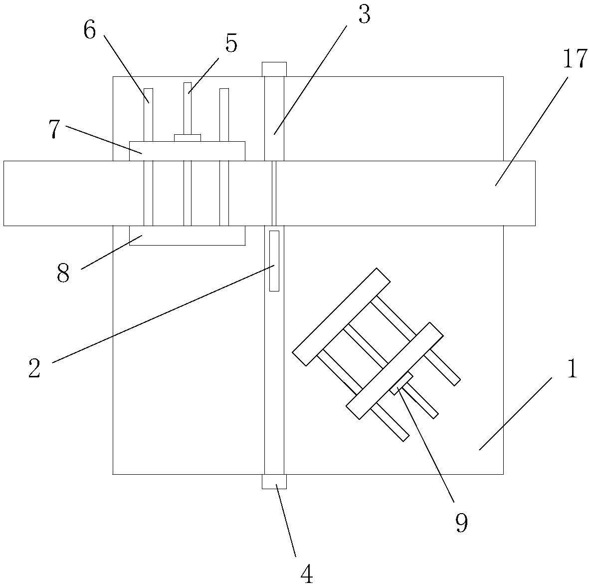
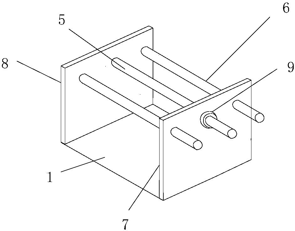
[0028] Among the two sets of clamping mechanisms, the group of threaded rods 5 parallel to the first rail 3 is suitable for cutting perpendicular to the direction of plastic profiles 17, and the group of threaded rods 5 and the first rail 3 at an angle of 45 degrees is suitable for profile Chamfer at both ends at 45 degrees.

[0029] When in use, select a suitable clamping mechanism according to processing requirements, and mark the cutting position on the plastic profile 17 . Rotate the adjustment wheel 9 to increase the distance between the sliding clamping part 7 and the fixed clamping part 8, then place the plastic profile 17 between the sliding clamping part 7 and the fixed clamping part 8, turn on the laser emitter, and push it back and forth For the plastic profile 17, when the light spot just falls on the marked cutting position, the adjusting wheel 9 is rotated in the opposite direction, so that the sliding clamping part 7 and the fixed clamping part 8 clamp the plast...


PUM


Abstract

The invention discloses a plastic profile cutting device comprising a machine platform, two clamping mechanisms and a cutting mechanism. The two clamping mechanisms are located on the two sides of a first rail dividing the machine platform into two parts. A threaded rod of one clamping mechanism is parallel to the first rail. A threaded rod of the other clamping mechanism and the first rail form an included angle of 45 degrees. The bottom edges of fixing and clamping portions of the two clamping mechanisms are tightly fixed to the machine platform. The cutting mechanism is arranged below the machine platform and comprises a second rail and a stepping motor arranged at one end of the second rail. The tail end of a lead screw of the stepping motor is connected with a motor support through abearing, wherein the motor support can slide along the second rail. A cutting motor is fixed to the motor support. A rotor of the cutting motor is fixedly provided with a saw blade. The upper portionof the saw blade is located inside the second rail. The two ends of the first rail are both provided with laser transmitters. The plastic profile cutting device improves the current situation that anexisting plastic profile cutting device is poor in safety and low in precision; and meanwhile, the edge of a profile can be conveniently cut into a 45-degree chamfer.

Description

technical field [0001] The invention relates to a plastic profile cutting device, in particular to a plastic profile cutting device suitable for making plastic-steel window frames. Background technique [0002] Plastic steel profiles are made of polyvinyl chloride plastic profiles plus steel linings. It is a commonly used building material and is widely used in the production of doors and windows in houses. It has better thermal insulation and sound insulation performance than traditional steel windows, wooden windows and aluminum alloy doors and windows. have been greatly improved. In the production of doors and windows of ordinary residential buildings, small-scale custom processing is often the main form. The construction party measures the relevant parameters of residential doors and windows on the spot and processes them independently. This process involves cutting large profiles, often using small general-purpose cutting equipment, which has poor safety and low precis...

Claims


Application Information

Patent Timeline
Patent Type & Authority Applications(China)
IPC IPC(8): B26D1/15B26D5/08B26D7/04B26D3/02
CPCB26D1/15B26D3/02B26D5/086B26D7/04
Inventor 王建志
Owner 天津市凯德瑞塑料异型材制造有限公司
Why Eureka
Try Eureka