Silicon carbide ingot slicing device and silicon carbide ingot slicing method

A silicon carbide crystal and silicon carbide technology is applied in the field of silicon carbide crystal rod slicing equipment and the slicing field of silicon carbide crystal rods, which can solve the problems of broken cutting lines, poor slicing quality of silicon carbide crystal rods, etc., and achieves an improved slicing quality. Effect

Active Publication Date: 2018-10-09
GLOBALWAFERS CO LTD
View PDF5 Cites 4 Cited by
  • Summary
  • Abstract
  • Description
  • Claims
  • Application Information

AI Technical Summary

Problems solved by technology

[0004] However, in the field of fixed wire slicing, most of the existing slicing equipment and operations for silicon carbide ingots use a line speed of 400 m / min to 700 m / min, which leads to poor slicing quality of silicon carbide ingots
However, if the line speed of existing slicing equipment and operations is increased, it will easily lead to problems such as cutting line breakage

Method used


Image

  • Silicon carbide ingot slicing device and silicon carbide ingot slicing method
  • Silicon carbide ingot slicing device and silicon carbide ingot slicing method
  • Silicon carbide ingot slicing device and silicon carbide ingot slicing method

Examples


Embodiment Construction

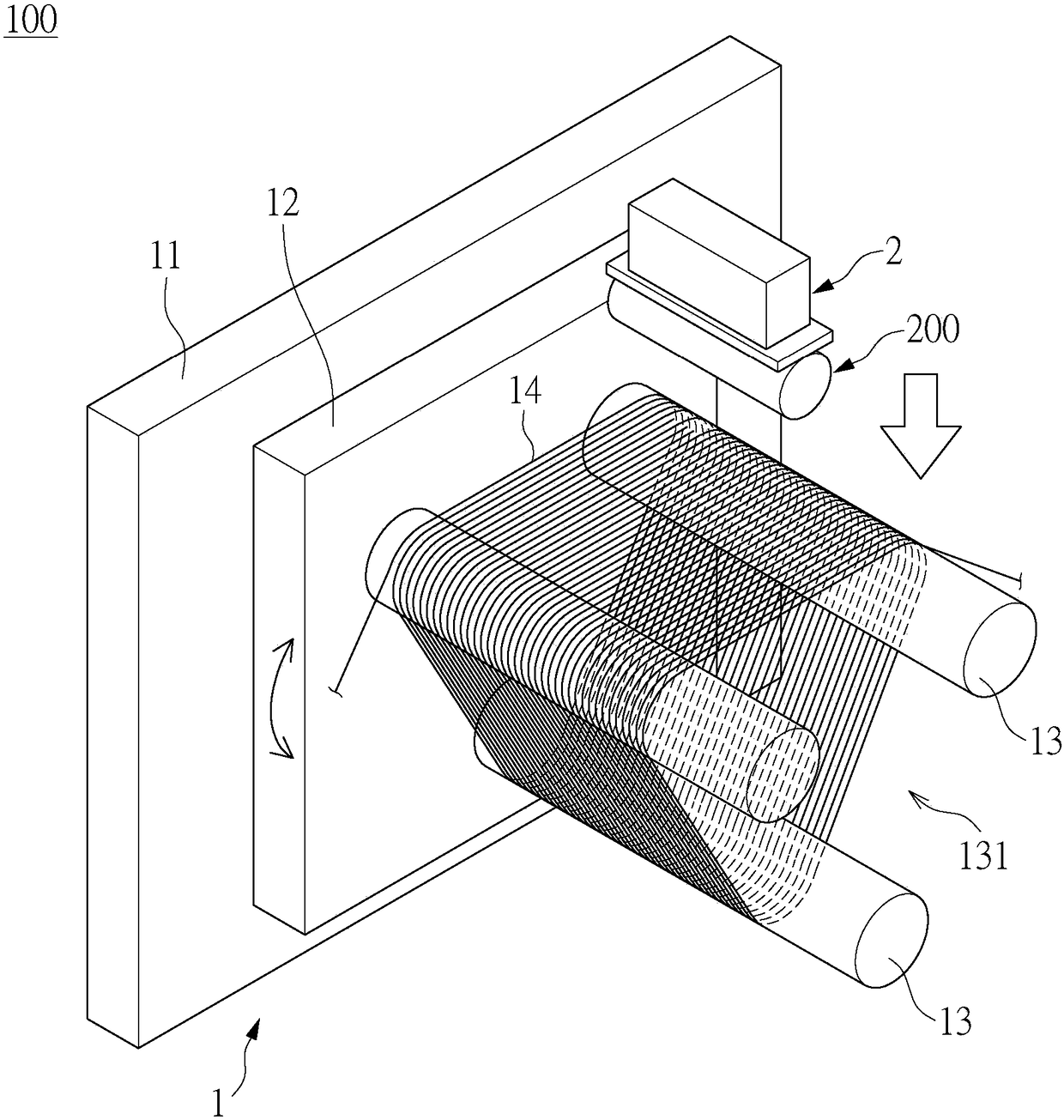
[0030] see Figure 3 to Figure 12 , is an embodiment of the present invention. It should be explained first that this embodiment corresponds to the relevant quantities and shapes mentioned in the drawings, and is only used to specifically illustrate the implementation of the present invention, so as to facilitate the understanding of the content of the present invention. It is not intended to limit the protection scope of the present invention.

[0031] Among them, this embodiment discloses a silicon carbide ingot slicing device 100 and a method for slicing a silicon carbide ingot, and to facilitate a clear understanding of this embodiment, the following will first describe the silicon carbide ingot slicing device 100, and then Next, the slicing method of the silicon carbide ingot is introduced.

[0032] Such as Figure 3 to Figure 5 , the silicon carbide ingot slicing device 100 is used to slice a cylindrical silicon carbide ingot 200 (such as a single crystal silicon carbi...


PUM


Abstract

The invention discloses a silicon carbide ingot slicing device and a silicon carbide ingot slicing method. The silicon carbide ingot slicing device comprises a swinging wire cutting device and a worktable for fixing a silicon carbide ingot. The swinging wire cutting device includes a fixing base, a swinging table which is disposed on the fixing base and can swing relatively, a plurality of rollers, and a cutting line which is movably wound around the plurality of rollers at a linear velocity of at least 1510 m / min. The plurality of rollers collectively define a slicing channel through which the silicon carbide ingot passes. The portions of the cutting line on the slicing channel are arranged in parallel at intervals and are defined as a plurality of operation line segments. During the process that the silicon carbide ingot is cut by the plurality of operation line segments, the swinging table swings relative to the fixing base, and the worktable can be moved at an adjusted feed speed.The adjusted feed speed gradually decreases from an initial speed to the lowest speed and then gradually increases to the final speed, so that the cutting line is not liable to break and effectively improve the slicing quality of the silicon carbide ingot.

Description

technical field [0001] The invention relates to a slicing device and a slicing method, in particular to a silicon carbide ingot slicing device and a silicon carbide ingot slicing method. Background technique [0002] At present, the slicing equipment for cutting ingots can be divided into two fields according to different working principles for people in the industry: one is free mortar slicing, and the other is fixed wire slicing. The following roughly discusses the respective cutting working principles of the above two fields. [0003] First, if figure 1 As shown, in the field of free mortar slicing, the cost of the slicing equipment is relatively low, but when cutting the ingot 1a, the slicing equipment drives the silicon carbide particles 31a in the cutting fluid 3a to roll through the wire 2a, and then continuously Cutting the crystal ingot 1a in this way is easy to cause uneven thickness of the wafer. What's more, debris is likely to be generated at the cut part of ...

Claims


Application Information

Patent Timeline
Patent Type & Authority Applications(China)
IPC IPC(8): B28D5/04B28D7/00
CPCB28D5/042B28D7/00
Inventor 林钦山吕建兴刘建成林嫚萱
Owner GLOBALWAFERS CO LTD
Why Eureka
Try Eureka