Rotary cap type lifting device for small building lift car
- Summary
- Abstract
- Description
- Claims
- Application Information
AI Technical Summary
Problems solved by technology
Method used
Image
Examples
Embodiment Construction
[0020] The specific implementation manners of the present application will be further described below in conjunction with the accompanying drawings.
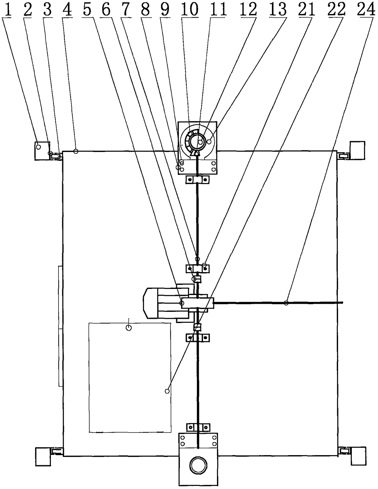
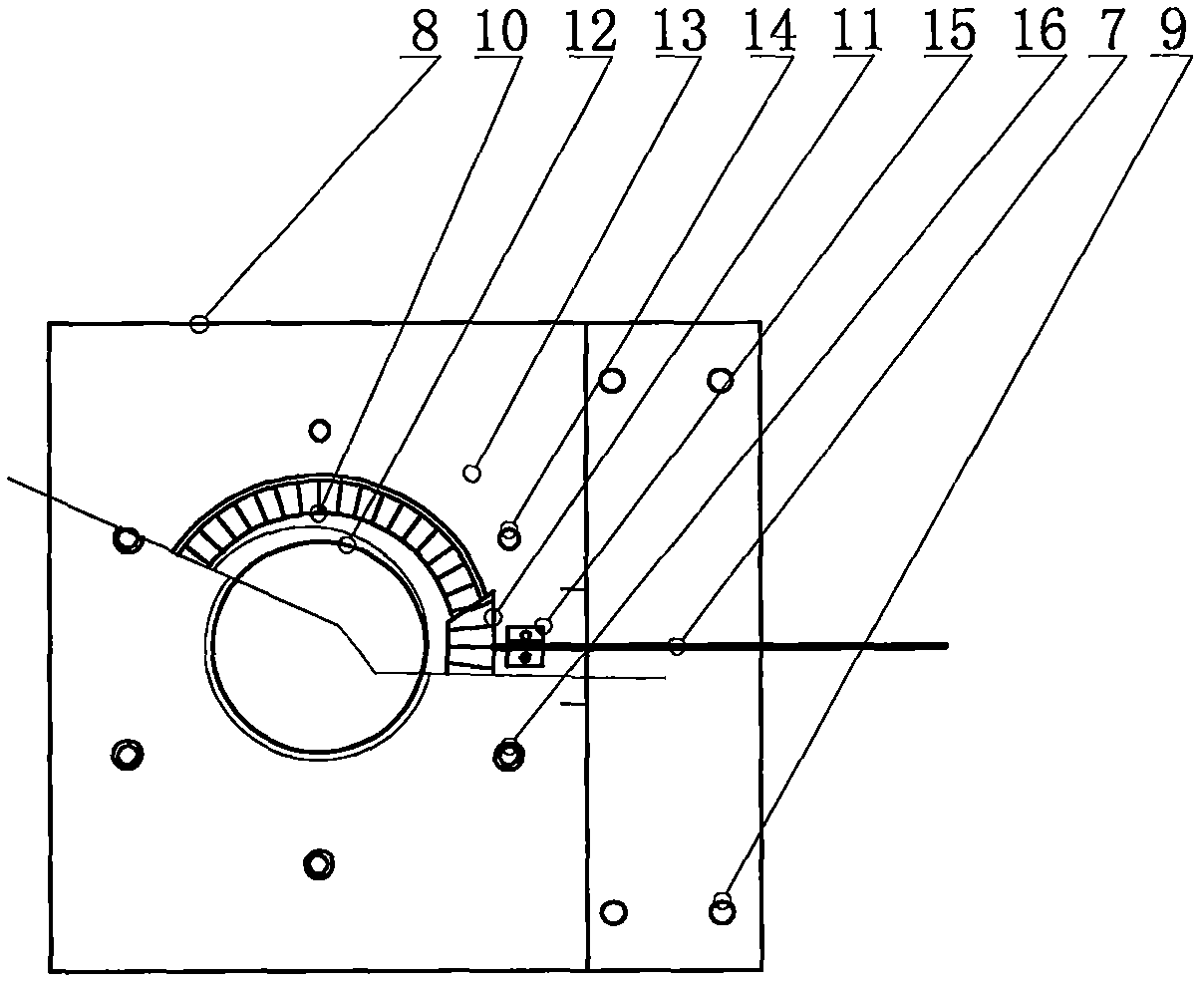
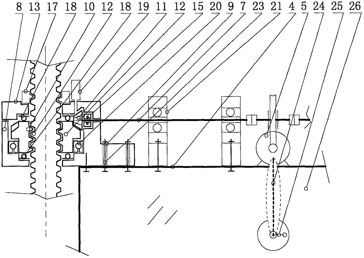
[0021] figure 1 Among them, including well frame 1, guide rail 2, pulley 3, car box 4, worm motor with brake 5, coupling 6, connecting shaft 7, shell 8, positioning screw hole 9, umbrella-shaped swivel 10, umbrella-shaped Gear 11, screw rod 12, gland 13, gland screw hole 14, bevel tooth positioning bearing 15, gland screw 16, dust-proof oil ring 17, plane bearing 18, oil cup 19, spinner positioning bearing 20, connecting shaft Bearing block 21, inspection window 22, screw 23, connecting shaft cable 24, crank handle 25, car wall 26, guide shaft frame 27 etc..
[0022] As shown in the figure, the present application is a rotary lifting device for a car in a small house, including a car mechanism, a rotary mechanism, and a control mechanism;
[0023] Described car mechanism comprises square pipe 1, guide rail 2, car box 4, pulley...
PUM
 Abstract
Description
Claims
Application Information
 - R&D
- Intellectual Property
- Life Sciences
- Materials
- Tech Scout
- Unparalleled Data Quality
- Higher Quality Content
- 60% Fewer Hallucinations
Browse by: Latest US Patents, China's latest patents, Technical Efficacy Thesaurus, Application Domain, Technology Topic, Popular Technical Reports.
© 2025 PatSnap. All rights reserved.Legal|Privacy policy|Modern Slavery Act Transparency Statement|Sitemap|About US| Contact US: help@patsnap.com


