Fault indicator based fault positioning method employing travelling wave-impedance method and used for double end power distribution network with branches

A technology for fault indicators and distribution network faults, which is applied to fault locations, instruments, and measuring circuits, and can solve problems such as positioning errors and positioning failures

Active Publication Date: 2018-10-09
广东电网有限责任公司清远英德供电局
View PDF6 Cites 9 Cited by
  • Summary
  • Abstract
  • Description
  • Claims
  • Application Information

AI Technical Summary

Problems solved by technology

Using the value of the speed of light or the approximate speed of light in the application will inevitably cause positioning errors
There are methods to eliminate the influence of traveling wave velocity by using the time when the fault initial traveling wave and the reflected wave of the fault point arrive at the bus, or use the time when the fault initial traveling wave, the reflected wave of the fault point and the reflected wave of the opposite end bus arrive at the bus to eliminate the influence of the wave velocity. This type of method performs fault location by detecting the reflected wave of the fault point or the reflected wave of the bus at the opposite end. When the reflected wave is attenuated to the point where it cannot be measured or there is no reflected wave, the location fails.

Method used


Image

  • Fault indicator based fault positioning method employing travelling wave-impedance method and used for double end power distribution network with branches
  • Fault indicator based fault positioning method employing travelling wave-impedance method and used for double end power distribution network with branches
  • Fault indicator based fault positioning method employing travelling wave-impedance method and used for double end power distribution network with branches

Examples


Embodiment Construction

[0045] In order to express the purpose and technical solution of the present invention simply and clearly, the following will be described in conjunction with the accompanying drawings and embodiments. The specific embodiments described here are only used to explain the present invention, not to limit the present invention.

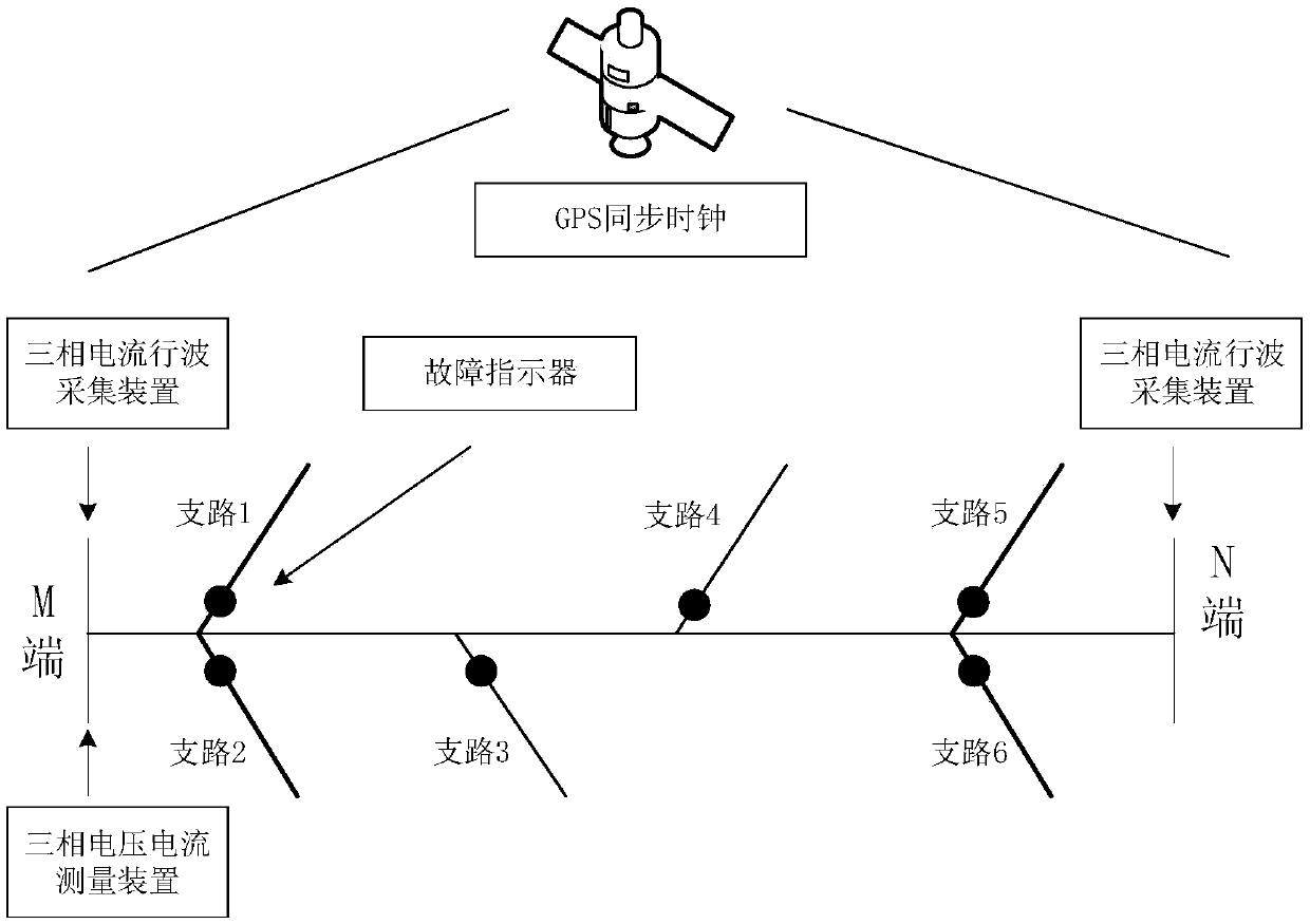
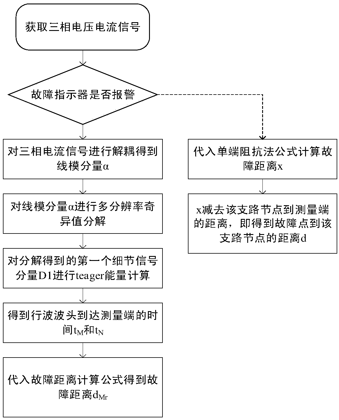
[0046] The transmission line system and positioning system of the double-ended distribution network with branches such as figure 1 As shown, it includes the installation of line system, fault indicator, double-ended traveling wave location system, and single-ended impedance location system. The positioning flow chart is as follows figure 2 shown, according to figure 2 The flow shown, the specific implementation steps are as follows:

[0047] Step 1: Install traveling wave signal acquisition devices at the first and last sections of the main line of the transmission line, that is, the M terminal and the N terminal, to obtain the three-phase current si...


PUM


Abstract

The invention discloses a fault indicator based fault positioning method employing a travelling wave-impedance method and used for a double end power distribution network with branches. Combination ofa double-end travelling wave method and a single-end impedance method based on GPS synchronization time check is utilized and a fault indicator is used in a cooperative manner. If a fault occurs andthe fault indicator on a branch does not send an alarm, it is indicated that the fault is in a main line. The double-end travelling wave method is utilized for positioning. If the fault indicator sends an alarm, it is indicated that the fault is in the branch. The single-end impedance method is utilized for positioning, and the position of the fault on the main line or the branch can be judged accurately. Wave head recognition of the double-end travelling wave method adopts a novel algorithm which is an MRSVD decomposition algorithm added with teager energy operators, and the travelling wave head arrival time point can be determined accurately. The method solves a problem that the double-end travelling wave method cannot determine branch faults and ensures the high precision of measurement. The novel wave head recognition algorithm overcomes shortcomings of a traditional wavelet method and a Hilbert-Huang Transform method. The method provided by the invention has high practical value.

Description

technical field [0001] The invention belongs to the field of electrical secondary systems, and in particular relates to a fault indicator-based fault location method for a double-terminal distribution network with branch circuits using the traveling wave-impedance method. Background technique [0002] Transmission line fault location technology is a research hotspot in the development of power system. Fast and accurate fault location after a line fault can help staff analyze the cause of the fault, troubleshoot and restore power in time, reduce the time and energy spent on line inspection, and reduce social and economic losses caused by power outages. In recent years, experts and scholars at home and abroad have proposed many fault location principles and algorithms, some of which have been made into devices, but the ranging accuracy still needs to be further improved. Therefore, the study of transmission line fault location has important practical significance. [0003] I...

Claims


Application Information

Patent Timeline
Patent Type & Authority Applications(China)
IPC IPC(8): G01R31/08
CPCG01R31/088Y04S10/52
Inventor 邹祁武胡金磊孙云莲叶良鹏唐小亮谢信霖付斌余军伟陈逸钦刘旺徐飞雄王玲吴莹卢珏
Owner 广东电网有限责任公司清远英德供电局
Why Eureka
Try Eureka