Superconducting magnet second-stage cooling apparatus and second-stage cooling method

A technology for superconducting magnets and secondary cooling, which is applied in the direction of superconducting magnets/coils, magnetic objects, electrical components, etc., can solve problems such as unavoidable, unreasonable economics, and adverse effects on the performance of superconducting coils, and achieve cost savings, The effect of ensuring performance

Pending Publication Date: 2018-10-09
杭州汉胜科磁体设备有限公司
View PDF0 Cites 5 Cited by
  • Summary
  • Abstract
  • Description
  • Claims
  • Application Information

AI Technical Summary

Problems solved by technology

Direct cooling usually uses liquid helium to be directly injected from the top of the container and leaked from the bottom. Since the temperature difference from room temperature to the temperature required by the superconducting magnet is too large, a large amount of liquid helium is required to cool the superconducting magnet to a predetermined low temperature, and each liter The unit price of liquid helium is more than 100 yuan, and a large amount of liquid helium is required to fill the liquid helium container, which is extremely unreasonable economically; the secondary or multi-stage cooling method is to first use a relatively economical low-temperature liquid, such as liquid nitrogen, so that the superconducting magnet device can be used from Cool from room temperature to cryogenic transition temperature, such as using liquid nitrogen to cool to minus 200°C (-77K), and then use pressurized gas, such as nitrogen or helium, to drive the cryogenic liquid, such as liquid nitrogen, from the bottom of the container to the top of the container for release, Then use low-temperature liquid from the top of the container, such as liquid helium, to inject it into the bottom of the container, and use a low-temperature composite, such as liquid helium, to cool the superconducting magnet to the predetermined working temperature of the magnet -270°C (4K). Although this method can save expensive Helium resources, but due to the use of other gases, such as liquid nitrogen, pre-cooling, it is inevitable that there will be residual remaining gases in the liquid helium container, such as nitrogen, when the superconducting magnet is cooled to a lower temperature, in the liquid helium container And superconducting magnet coils will form solid matter of other gases, such as nitrogen solid sand, which will adversely affect the performance of superconducting coils

Method used


Image

  • Superconducting magnet second-stage cooling apparatus and second-stage cooling method
  • Superconducting magnet second-stage cooling apparatus and second-stage cooling method
  • Superconducting magnet second-stage cooling apparatus and second-stage cooling method

Examples


Embodiment 1

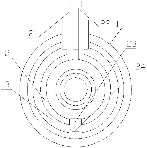
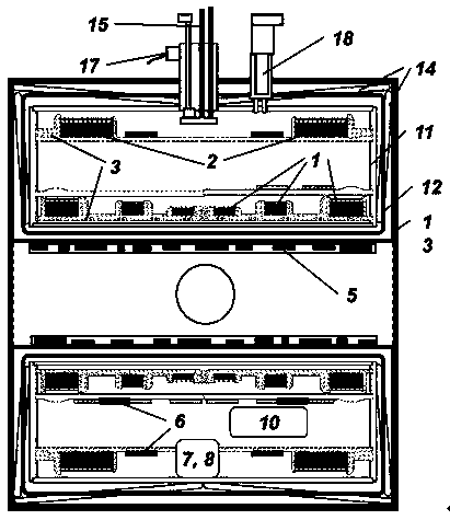
[0013] Embodiment 1: with reference to attached figure 1 and 2 . A secondary cooling device for a superconducting magnet includes a superconducting magnet cooling device 1. The manufacture of the superconducting cooling device 1 is based on the prior art, and will not be described here. In the present invention, on the basis of the superconducting magnet cooling device 1, a cooling pipeline 2 is provided in the liquid helium container 3 in the superconducting magnet cooling device. At the outlet, a three-way control valve 23 is connected in series in the cooling pipeline 2 and the outlet of the three-way control valve 23 communicates with the cavity of the liquid helium container 3 .

[0014] The cooling pipeline 2 is one group or multiple groups, whether it is one group or multiple groups, the cooling pipeline 2 is in contact with the coil surface of the superconducting magnet located in the liquid helium container 3, and the cooling pipeline 2 is provided with heater.

...

Embodiment 2

[0019] Embodiment 2: On the basis of Embodiment 1, a cooling method of a superconducting magnet secondary cooling device, 1) liquid nitrogen passes through the refrigeration of the cooling pipeline 2 in the liquid helium container 3, so that the liquid helium valve container 3 The superconducting magnet inside is cooled from room temperature to minus 200°C (-77K); 2) Use pressurized fluid to drive liquid nitrogen from the cooling pipeline 2 to the top of the container for release; 3) Connect it in series to the cooling pipeline 2 The three-way control valve 23 is opened, and since the outlet of the three-way control valve 23 is connected to the liquid helium container 3, the liquid helium is injected into the cooling pipeline 2 at this time because the three-way control valve 23 liquid outlet connected in series on the cooling pipeline enters the liquid helium container 3 Inside, liquid helium cools the superconducting magnet to the predetermined magnet operating temperature -2...


PUM


Abstract

The invention relates to a superconducting magnet second-stage cooling apparatus which enables a superconducting coil to be cooled from the room temperature to a needed ultra-low temperature state without generating nitrogen sand particles in a liquid nitrogen container and the superconducting coil, and a second-stage cooling method. The superconducting magnet second-stage cooling apparatus comprises a superconducting magnet cooling apparatus; a cooling pipeline is arranged in the liquid nitrogen container of the superconducting magnet cooling apparatus; the inlet and the outlet of the coolingpipeline are coolant inlet and outlet respectively; and a three-way control valve is connected in the cooling pipeline in series, and the outlet of the three-way control valve is connected with the liquid nitrogen container. Advantages are achieved as follows: a condition that the residual liquid nitrogen in the liquid nitrogen container and the superconducting coil is changed into residual solidnitrogen sand particles when the superconducting magnet is cooled to a lower temperature caused by existence of the residual nitrogen in the liquid nitrogen container in the prior art can be solved fundamentally, so that no liquid nitrogen residue is realized, and it is ensured that the performance of the superconducting coil is not influenced; and in addition, compared with full liquid nitrogencooling, each superconducting magnet cooling apparatus can save cost by 70% or above compared with that in the background technology, so that unexpected economic benefits and social benefits are achieved.

Description

technical field [0001] The invention relates to a secondary cooling device for a superconducting magnet, which can not only lower the superconducting coil from room temperature to the required ultra-low temperature state, but will not produce solid sand particles formed by other gases in the liquid helium container and the superconducting coil device The invention relates to a secondary cooling method, which belongs to the field of superconducting magnet cooling device manufacturing. Background technique [0002] Superconducting magnets have been widely used in magnetic resonance equipment and other fields that require stable and high magnetic field strength. A coil made of superconducting material generates a strong magnetic field through a large current, and through the current closed-loop technology of superconducting material characteristics, when the external current is gradually removed, the superconducting coil maintains its operating current and remains unchanged for...

Claims


Application Information

Patent Timeline
Patent Type & Authority Applications(China)
IPC IPC(8): H01F6/04
CPCH01F6/04
Inventor 沈伟俊
Owner 杭州汉胜科磁体设备有限公司
Why Eureka
Try Eureka