Base plate device used for printing circuit board plug holes

A technology for printed circuit boards and plug holes, which is applied in the fields of printed circuits, printed circuits, and printed circuit manufacturing, can solve problems affecting production efficiency, plug holes are not full, and increase costs, so as to improve the efficiency and quality of plug holes, prevent Ink deposition clogging, effect of saving processing cost

Pending Publication Date: 2018-10-09
湖北荣宝电子科技有限公司
View PDF5 Cites 1 Cited by
  • Summary
  • Abstract
  • Description
  • Claims
  • Application Information

AI Technical Summary

Problems solved by technology

This method of plug hole operation has the following disadvantages: 1. Increased cost: due to the different sizes and plug holes of different material numbers, the backing plate cannot be shared and needs to be replaced repeatedly. The backing plate needs to be made separately according to the material number. After a single material number is produced, The backing plate must be scrapped and cannot be reused, which increases the cost of drilling and raw material costs of the backing plate, and consumes man-hours; 2. Affects production efficiency: the holes of the backing plate, the plug hole plate and the mesh plate must be aligned together. The operation is cumbersome, and this operation must be repeated every time the material number is changed, which affects the production efficiency; 3. The quality is affected: the air permeability of the backing plate is not very good, and there are easy air bubbles when plugging the holes, resulting in the plug holes not being full. It is connected up and down, and the ink entering the hole of the backing plate is easy to contaminate the printing machine table and the plug hole plate

Method used


Image

  • Base plate device used for printing circuit board plug holes
  • Base plate device used for printing circuit board plug holes
  • Base plate device used for printing circuit board plug holes

Examples


Embodiment Construction

[0016] The following will clearly and completely describe the technical solutions in the embodiments of the present invention with reference to the accompanying drawings in the embodiments of the present invention. Obviously, the described embodiments are only some, not all, embodiments of the present invention. Based on the embodiments of the present invention, all other embodiments obtained by persons of ordinary skill in the art without making creative efforts belong to the protection scope of the present invention.

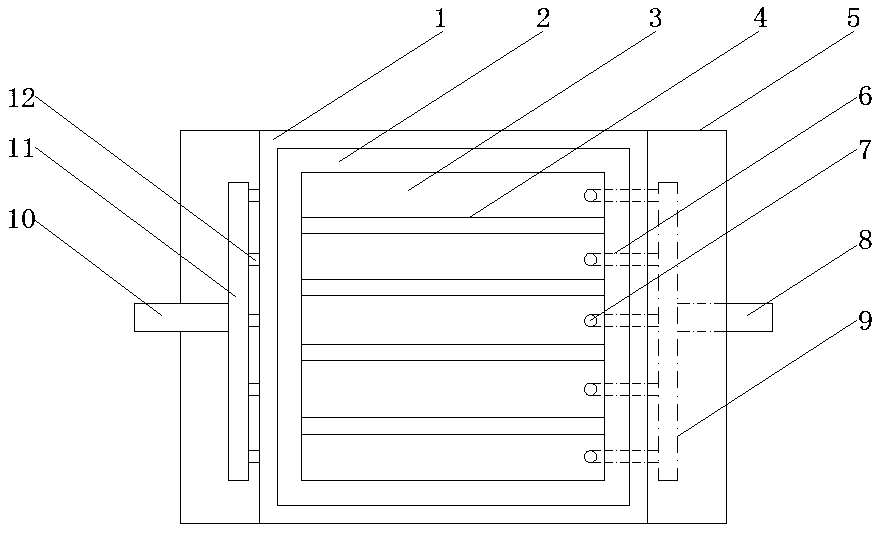
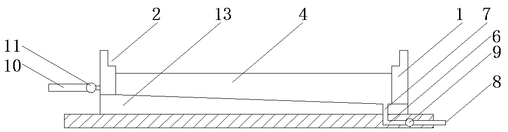
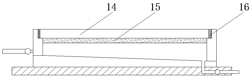
[0017] see Figure 1~3 , in an embodiment of the present invention, a backing plate device for a printed circuit board plug hole includes a frame plate 1, a limiting groove 2, a diversion cavity 3, a diversion plate 4, a fixing seat 5, a water outlet branch pipe 6, a drain Water tank 7, water outlet main pipe 8, water outlet collecting pipe 9, water inlet main pipe 10, water inlet distribution pipe 11, water inlet branch pipe 12, slope bottom plate 13, sealing...


PUM


Abstract

The invention discloses a base plate device for printed circuit board plug holes. The base plate device comprises a frame plate, a flow guide plate, a fixed base, a water outlet collecting pipe and awater inlet shunting pipe, and an inclined bottom plate is fixedly arranged at the top of the fixed base and located in the middle position, the width of the inclined bottom plate is the same as the width of the fixed base, frame plates are fixedly arranged at the top of the inclined bottom plate and located at the four edges, limiting grooves are formed in the top of the frame plates, and the limiting grooves are formed in the inner sides of the frame plates, a cavity is formed between the inclined bottom plate and the frame plates, a plurality of flow guide plates are fixedly arranged in thecavity, and the four flow guide plates divide the cavity into five flow guide cavities, each flow guide cavity is an independent cavity with a trapezoid cross section, and water inlet branch pipes are fixedly arranged on the left sides of the flow guide cavities. The base plate device used for printing the circuit board plug holes is simple in structure, convenient to use, convenient to dischargeresidual oil ink, convenient to clean after being used, and capable of improving the utilization rate, reducing the processing cost and being worthy of popularization.

Description

technical field [0001] The invention relates to a backing plate, in particular to a backing plate device used for plugging holes of printed circuit boards. Background technique [0002] At present, the plugging operation method commonly used in the industry is screen printing plugging, because the main equipment required - the printing machine is generally owned by the industry, and the required tools - screens, scrapers, backing plates and alignment needles And so on are also standing materials. The screen printing plug hole operation process is roughly as follows: the hole position of the backing plate and the screen plate is the same as that of the plug hole plate, the backing plate is fixed on the printing machine table, and the backing plate, plug hole plate and screen plate are arranged from bottom to bottom. The top is stacked and positioned in turn, the holes of the three are opposite to each other, the scraper is printed on the screen, and the printing pressure pre...

Claims


Application Information

Patent Timeline
Patent Type & Authority Applications(China)
IPC IPC(8): H05K3/00
CPCH05K3/0094H05K2201/0959
Inventor 呼宝宝曾凡伍
Owner 湖北荣宝电子科技有限公司
Why Eureka
Try Eureka