Sheet metal stamping device

A punching device, sheet metal technology, applied in the direction of feeding device, positioning device, storage device, etc., can solve the problems of reducing the yield rate, affecting the processing of sheet metal parts, residual debris, etc., to improve the yield rate and improve stamping accuracy. resistance to scratches and damage from debris

Pending Publication Date: 2018-10-12
范媛媛
View PDF8 Cites 18 Cited by
  • Summary
  • Abstract
  • Description
  • Claims
  • Application Information

AI Technical Summary

Problems solved by technology

[0004] The purpose of the present invention is to provide a sheet metal punching device to solve the problem that the existing punching device proposed in the above background technology needs to replace different clamps when fixing sheet metal parts of different specifications, so as to improve the punching of sheet metal parts. Accuracy, when processing and

Method used


Image

  • Sheet metal stamping device
  • Sheet metal stamping device
  • Sheet metal stamping device

Examples


Example Embodiment

[0025] The technical solutions in the embodiments of the present invention will be clearly and completely described below in conjunction with the accompanying drawings in the embodiments of the present invention. Obviously, the described embodiments are only a part of the embodiments of the present invention, rather than all the embodiments. Based on the embodiments of the present invention, all other embodiments obtained by those of ordinary skill in the art without creative work shall fall within the protection scope of the present invention.
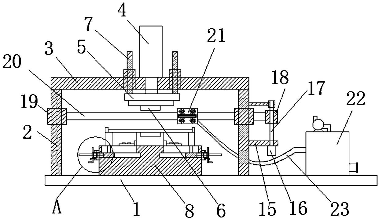
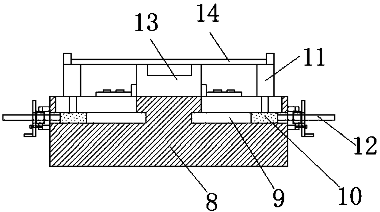
[0026] See Figure 1-7 , The present invention provides a technical solution: a sheet metal stamping device, comprising a base 1, the top of the base 1 is provided with a stamping table 8, the top of the stamping table 8 is uniformly provided with a sliding groove 9 annularly, the sliding The inner cavity of the slot 9 is provided with a slider 10, the top of the slider 10 is connected with a stamping support seat 11, the top of the stam...


PUM


Abstract

The invention discloses a sheet metal stamping device. A cylinder rod of an air cylinder is connected to the left side of a movable frame, a first bracket is arranged on the right side of a support column, a first motor is installed at the bottom of the first bracket, a second threaded rod is connected to an output shaft of the first motor, a first threaded sleeve is in threaded connection to theouter side of the second threaded rod, and the first threaded sleeve is fixedly connected with the outer side of a movable barrel. According to the sheet metal stamping device, a plurality of stampingsupport seats are arranged, so that different shapes of sheet metal pieces of different sizes can be positioned, supported and clamped by the device, the different sheet metal pieces are convenientlystamped, and the stamping precision of the sheet metal pieces is increased; according to the sheet metal stamping device, a stamping head is brushed by a first bristle brush wheel and a second bristle brush wheel, and brushed chippings are sucked by a hollow plate, so that the stamping head is kept clean, the rate of finished products of the sheet metal pieces is increased, and the surfaces of the sheet metal pieces are prevented from being scratched and damaged by the chippings.

Description

technical field [0001] The invention relates to the technical field of stamping equipment, in particular to a sheet metal stamping device. Background technique [0002] Sheet metal, a processing technology, sheet metal has not yet had a relatively complete definition. According to a definition in a foreign professional journal, it can be defined as: sheet metal is a comprehensive cold processing process for metal sheets (usually below 6mm), including shearing, punching / cutting / compositing, folding, riveting, splicing, Forming (such as car body), etc. Its remarkable feature is that the thickness of the same part is consistent. [0003] Sheet metal parts need to be stamped during sheet metal processing. The existing stamping device needs to replace different fixtures when fixing sheet metal parts of different specifications to improve the stamping accuracy of sheet metal parts. When stamping sheet metal parts, various fixtures are required, which are inconvenient to replace...

Claims


Application Information

Patent Timeline
IPC IPC(8): B21D43/00B21D43/20B21D37/00B08B1/04
CPCB08B1/002B08B1/04B21D37/00B21D43/003B21D43/20
Inventor 罗诗敏柴霞霞周鹏陈昊李闻淼
Owner 范媛媛
Why Eureka
Try Eureka