Stamping device for machining inner ring and outer ring of bearing

A punching device, inner and outer ring technology, applied in the field of bearing processing, can solve the problems of low safety factor of manual reclaiming, lower punching efficiency, complicated punching steps, etc., and achieve the effects of facilitating subsequent collection, improving safety, and convenient operation

Active Publication Date: 2021-09-03
临清市同兴轴承锻造有限公司
View PDF8 Cites 0 Cited by
  • Summary
  • Abstract
  • Description
  • Claims
  • Application Information

AI Technical Summary

Problems solved by technology

[0003] In the prior art, it is necessary to manually take, unload, and transfer materials during stamping, which makes the stamping steps cumbersome, time-consuming and laborious, reduces the efficiency of stamping, and the safety factor of manual retrieval is low. Don't collect the waste from stamping very well

Method used


Image

  • Stamping device for machining inner ring and outer ring of bearing
  • Stamping device for machining inner ring and outer ring of bearing
  • Stamping device for machining inner ring and outer ring of bearing

Examples


Embodiment 1

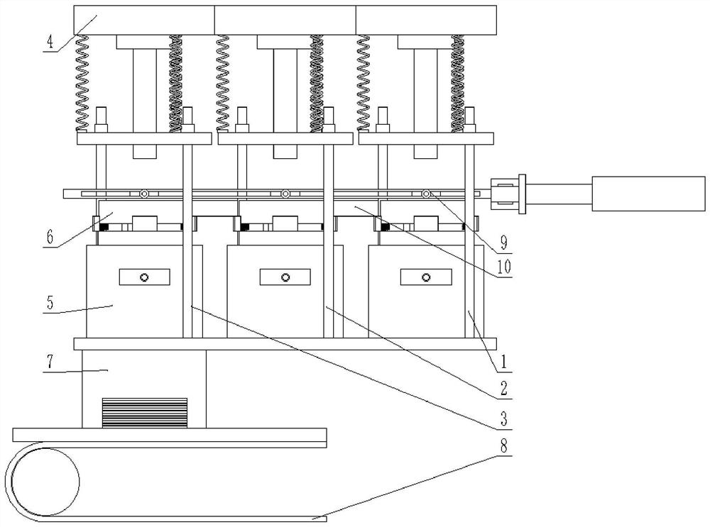
[0041] A stamping device for processing inner and outer rings of bearings, such as Figure 1-Figure 4 As shown, it includes a pier roughing station 1, a punching station 2 and a punching station 3 stations arranged in sequence. The stations are respectively provided with a stamping mechanism 4 and a height-adjustable stamping seat 5. A transition plate 10 is arranged between the stations, and the top surface of the transition plate 10 is flush with the bottom surface of the materials on the stations. When the material is moved along different stations, the transition plate 10 plays a supporting role to prevent the material from falling between the stations due to accidents and ensure smooth processing.

[0042] Described stamping mechanism 4 comprises the stamping head that has power source, and the upper mold that adapts to lower mold 6 is installed on one side of stamping head, is provided with damping spring between described power source and upper mold, and upper mold and ...

Embodiment 2

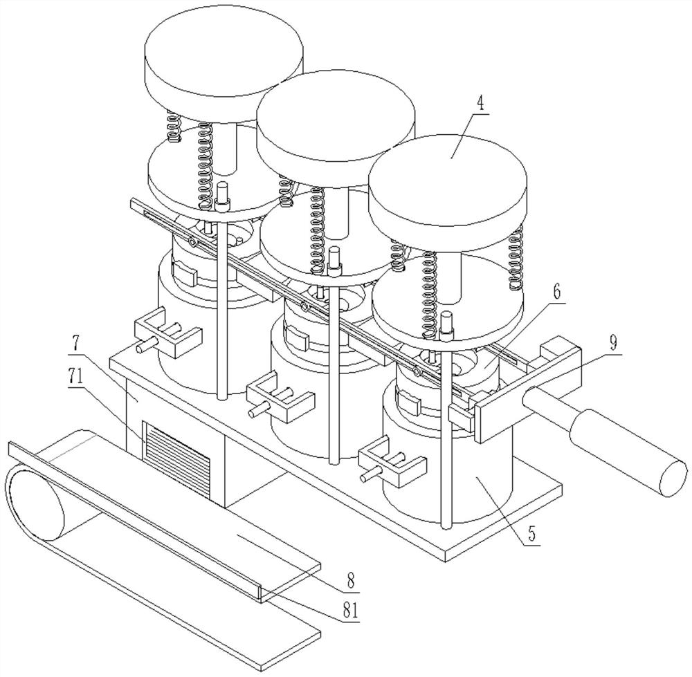
[0053] On the basis of Example 1, such as Figure 4 As shown, an opening 71 is provided on one side of the waste collection box 7, and an inclined guide plate 72 is movably installed in the lower part of the collection box, and one end of the guide plate 72 presses against the inner wall of the box. The opening 71 and the guide plate 72 correspond to the conveying line 8 . The guide plate 72 can play a buffering role to prevent unnecessary damage to the conveying line 8 caused by waste materials falling directly onto the conveying line 8 .

[0054] One side of the waste collection box 7 is provided with an adjusting rod 73 for moving the guide plate 72, and one side of the waste collection box 7 is provided with a through hole, and a connecting shaft is arranged in the through hole, and the adjusting rod 73 is set on the connecting shaft. ; The adjusting rod 73 is provided with a long slot matched with the connecting shaft, so that the position of the adjusting rod 73 in the ...

Embodiment 3

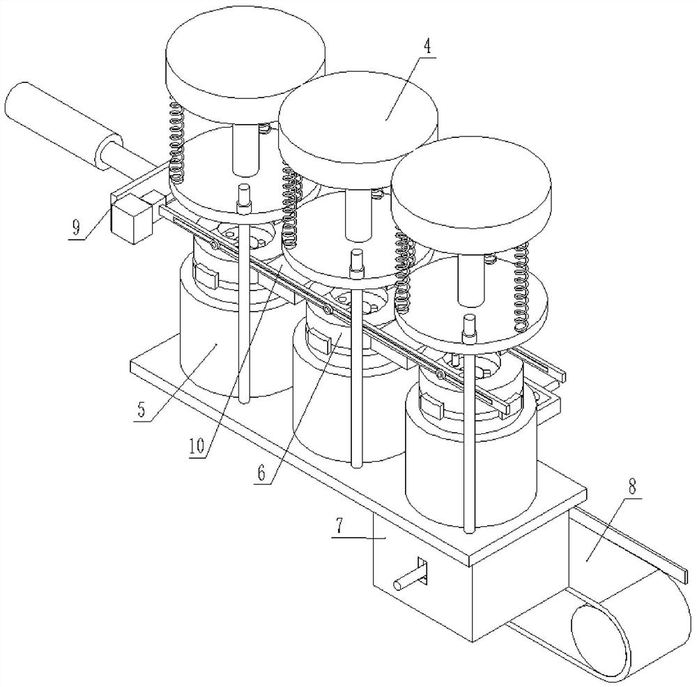
[0059] On the basis of Example 1 and Example 2, as Figure 7 and Figure 8 As shown, a relatively movable clamp assembly 9 is provided on one side of the station, and the clamp assembly 9 moves along the direction of the roughing station 1, the punching station 2 and the punching station 3. That is to clamp the processed materials at different stations and move to the next station. After reaching the next station, the clamp assembly 9 releases the materials, so that the materials fall to the next station and are processed accordingly. At this time, the clamp Component 9 resets to move the material next time.

[0060] The clamp assembly 9 includes a mounting rod 91 with a clamp 93, a screw nut mechanism 95, a cylinder 96 and a riser 97, and one end of the mounting rod 91 is provided with a screw nut mechanism 95 that makes it move relatively. The cooperation of the lead screw nut drives the installation rod 91 to move, and then the clamp 93 clamps or loosens the material. A ...


PUM


Abstract

The invention discloses a stamping device for machining an inner ring and an outer ring of a bearing. The stamping device comprises an upsetting station, a notching station and a stamping station which are sequentially arranged, wherein a stamping mechanism, a height-adjustable stamping seat and a lower die are respectively arranged on the stations, the lower die capable of being reset is arranged on one side of the stamping seat, a resettable ejector rod is mounted on the inner side of the stamping seat, and one end of the ejector rod is matched with a material in the lower die; a waste collecting box is arranged on the lower portion of the stamping seat on the stamping station, and a conveying line with a baffle is arranged on one side of the waste collecting box. The structure design is reasonable, materials are machined according to the sequence of upsetting, notching and punching, and the machining difficulty can be reduced through the sequence. The lower die and the ejector rod are installed through an elastic piece, on the basis that the stamping effect is not affected, the damping effect can be achieved, the stamping mechanism is prevented from making direct and rapid contact with the lower die to generate noise, and materials on the lower die can form displacement difference relative to cut-off waste materials.

Description

technical field [0001] The invention relates to the technical field of bearing processing, in particular to a stamping device for processing inner and outer rings of a bearing. Background technique [0002] Bearing is an important part of contemporary mechanical equipment. Its main function is to support the mechanical rotating body, reduce the friction coefficient during its movement, and ensure its rotation accuracy. Bearings usually include bearing rings, cages and rolling elements, and bearing rings include outer rings and inner rings. When processing bearing rings, it is generally necessary to heat the bar raw material first, then cut the bar into round blocks one by one, and then punch the round blocks through a stamping device, and pre-punch through holes on the round blocks for subsequent Perform hole reaming. [0003] In the prior art, it is necessary to manually take, unload, and transfer materials during stamping, which makes the stamping steps cumbersome, time-...

Claims


Application Information

Patent Timeline
Patent Type & Authority Applications(China)
IPC IPC(8): B21D35/00B21D43/00B21D43/04B21D45/00B21D53/10
CPCB21D35/002B21D43/003B21D43/04B21D45/00B21D53/10Y02P70/10
Inventor 汪庆刚王延虎邢丕伟田兆志
Owner 临清市同兴轴承锻造有限公司
Why Eureka
Try Eureka