Assembling equipment for right-angled double-end gripper

A technology of assembly equipment and double-headed clamps, applied in assembly machines, metal processing equipment, manufacturing tools, etc., can solve the problem that cannot be directly applied to right-angle double-headed clamps, etc., and achieve the effect of making up for market vacancies

Active Publication Date: 2018-10-12
海盐久力零部件科技有限公司
View PDF11 Cites 9 Cited by
  • Summary
  • Abstract
  • Description
  • Claims
  • Application Information

AI Technical Summary

Problems solved by technology

[0003] In actual use, different pliers are designed according to different needs, such as right-angle double-head clamps, which are suitable for double-wire cutting, but there is no automatic assembly machine for right-angle double-head clamps in the prior art, so It is necessary to design a device for right-angle double-ended clamps
[0004] Chinese Patent No.: Publication No. CN201736017U, a horizontal dual-hydraulic scissors handle assembly machine, including a workbench, wherein two groups of hydraulic cylinders are installed side by side in the same direction on the workbench, each group of hydraulic cylinders is equipped with pushers in front of it. One end of the push plate is fixedly connected with the oil rod of the hydraulic cylinder, the bottom of the push plate is slidably connected with the square groove guide rail, the edge of the push plate is equipped with a proximity switch, and the other end of the push plate is There is a mold base plate in front of one end; a foot switch is installed under the workbench, and the foot switch is connected to the hydraulic cylinder through a hydraulic system, which solves the problem of handle assembly, but cannot be directly applied to the assembly of right-angle double-head clamps among

Method used


Image

  • Assembling equipment for right-angled double-end gripper
  • Assembling equipment for right-angled double-end gripper
  • Assembling equipment for right-angled double-end gripper

Examples


Embodiment Construction

[0029] Below in conjunction with accompanying drawing and embodiment of description, specific embodiment of the present invention is described in further detail:

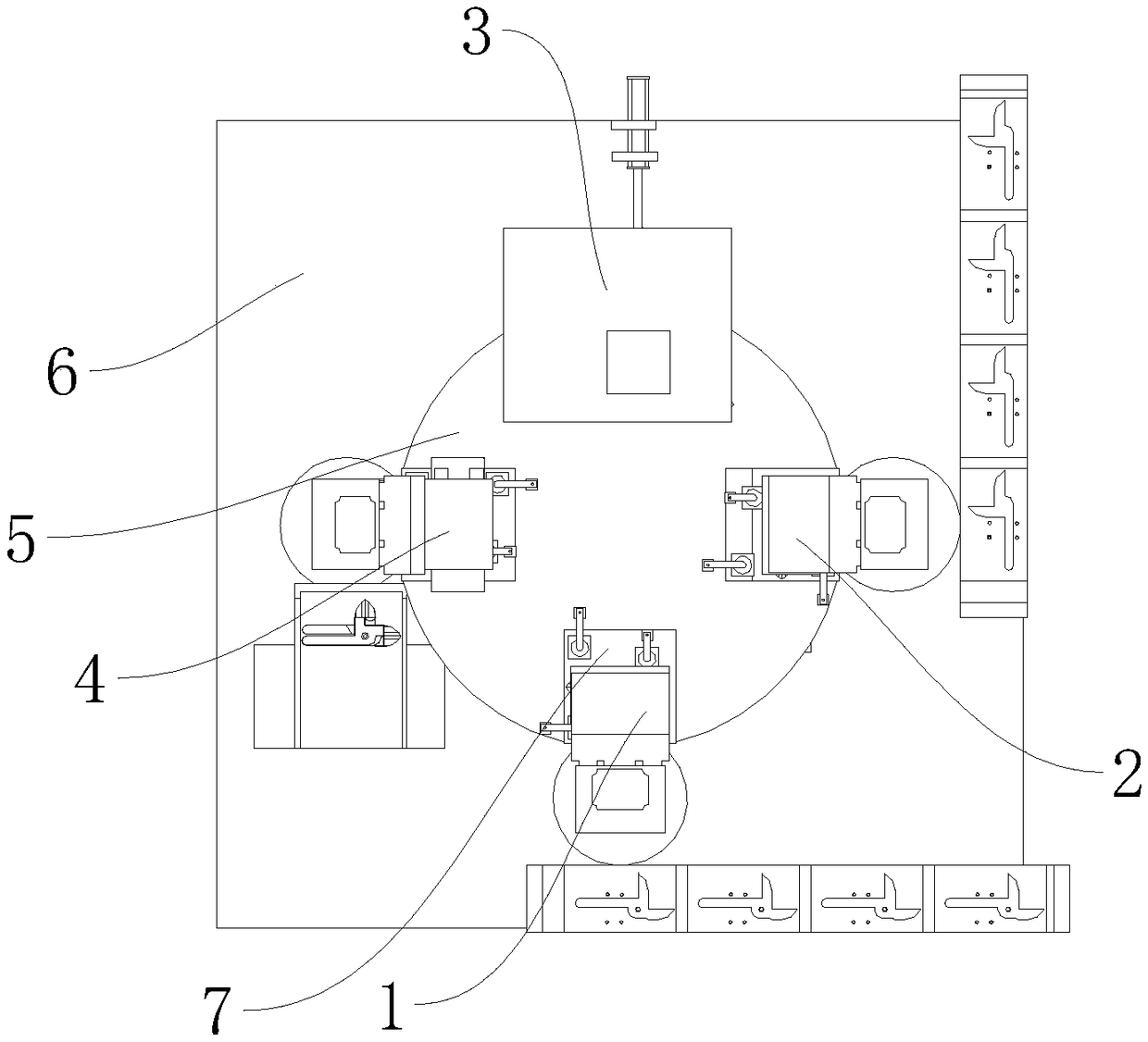
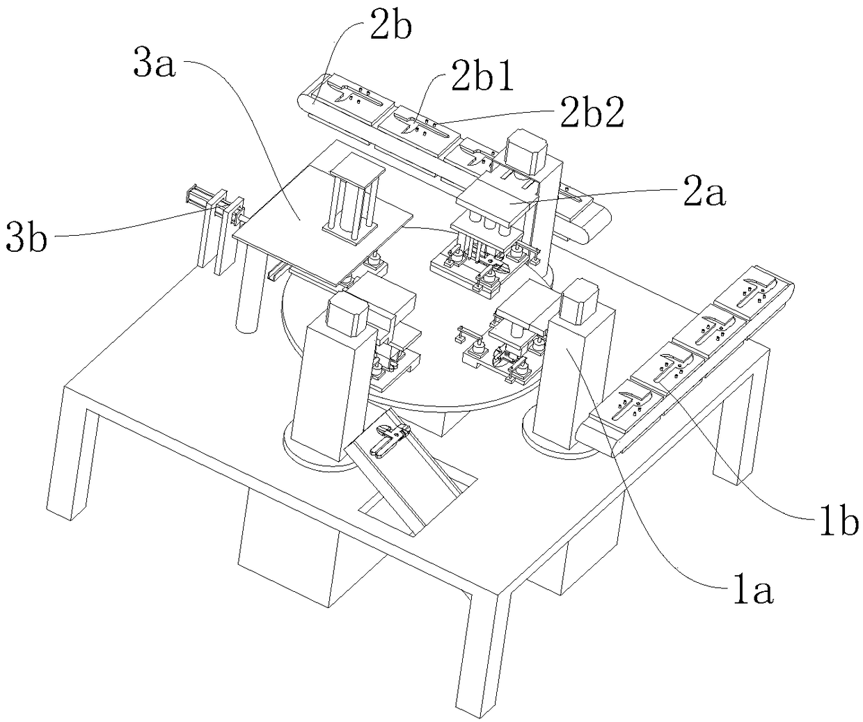
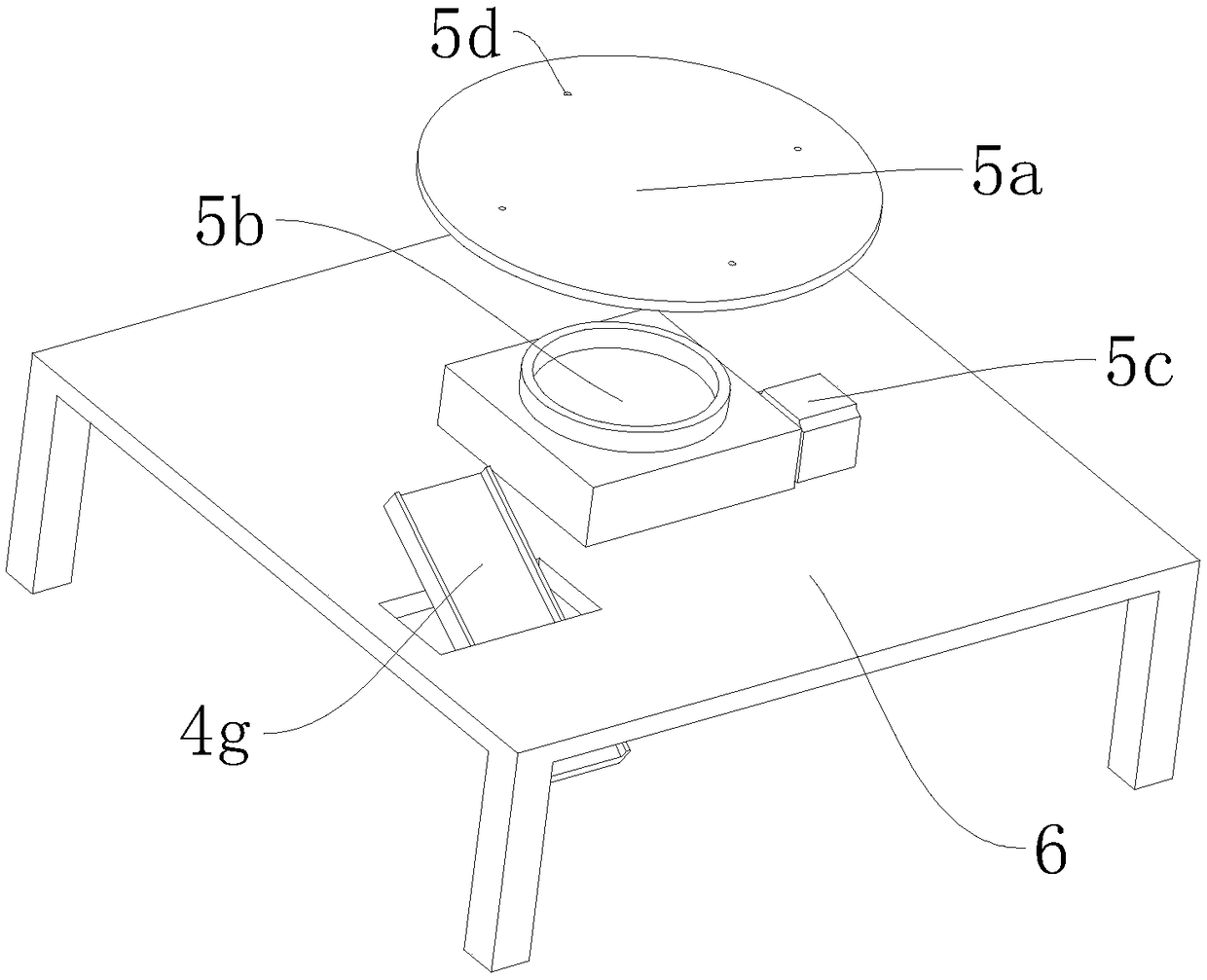
[0030] refer to Figure 1 to Figure 10The shown assembly equipment of a right-angled double-head clamp includes a base 6, and also includes a rotating assembly 5, a first clamp body feeding station 1, a second clamp body feeding station 2, and a clamp body riveting worker. position 3 and unloading station 4, the rotary assembly 5 includes a turntable 5a, an indexing plate 5b and a stepping motor 5c, the indexing plate 5b is fixedly arranged on the base 6, and the output shaft of the stepping motor 5c is connected to the The indexing plate 5b is connected by transmission, and the turntable 5a is set on the indexing plate 5b in a horizontal state. The turntable 5a is also provided with four workpiece fixtures 7 for fixing the workpiece, and the four workpiece fixtures 7 are arranged along the circumference of the turn...


PUM


Abstract

The invention relates to the field of gripper assembly, in particular to assembling equipment for a right-angled double-end gripper. The assembling equipment comprises a base and also comprises a rotary assembly, a first gripper body loading station, a second gripper body loading station, a gripper body riveting station and an unloading station, wherein the rotating assembly comprises a rotating disc, an index plate and a stepping motor; the index plate is fixedly arranged on the base; the output shaft of the stepping motor is in transmission connection to the index plate; the rotating disc ishorizontally arranged on the index plate; the first gripper body loading station, the second gripper body loading station, the gripper body riveting station and the unloading station are successivelyarranged around the clockwise direction of the rotating disc; the first gripper body loading station comprises a first gripper body loading mechanical arm and the second gripper body loading stationcomprises a second gripper body loading mechanical arm; the gripper body riveting station comprises a riveting assembly for riveting a first gripper body and a second gripper body and a rivet loadingassembly; and the unloading station comprises an unloading mechanical arm, so that the problem of automatically assembling the double-end gripper is solved.

Description

technical field [0001] The invention relates to the field of pliers assembly, in particular to an assembly device for right-angle double-headed pliers. Background technique [0002] Pliers are a hand tool used to clamp and fix workpieces or to twist, bend, and cut wires. The shape of the pliers is V-shaped, usually including three parts: the handle, the pliers jaw and the pliers mouth. The pliers are generally made of carbon structural steel. heat treatment. The handles of the pliers are designed in three styles: straight handle, curved handle and bow handle according to the gripping form. The pliers are often in contact with live conductors such as wires, so the handles are generally covered with protective tubes made of insulating materials such as polyvinyl chloride to ensure the safety of the operator. [0003] In actual use, different pliers are designed according to different needs, such as right-angle double-head clamps, which are suitable for double-wire cutting, ...

Claims


Application Information

Patent Timeline
Patent Type & Authority Applications(China)
IPC IPC(8): B23P21/00
CPCB23P21/006
Inventor 夏文斌
Owner 海盐久力零部件科技有限公司
Why Eureka
Try Eureka