
Efficient cutting device for composite material production and processing

A technology of composite materials and cutting devices, which is applied in metal processing and other directions, can solve the problems of ineffective adjustment of equipment, inconvenient use, and low efficiency of equipment, and achieve the effects of reducing vibration, convenient use, and convenient cutting

Inactive Publication Date: 2018-10-12
金寨县鑫和新能源科技有限公司
View PDF6 Cites 7 Cited by
  • Summary
  • Abstract
  • Description
  • Claims
  • Application Information

AI Technical Summary

Problems solved by technology

[0003] During the production and processing of composite materials, it is often necessary to cut the material, but the current cutting equipment has a simple structure, and the equipment is often unable to be effectively adjusted during the cutting process, so it is generally necessary to manually adjust the orientation of the cut composite material. Cutting, so not only the work efficiency of the equipment is low, but also it is very inconvenient for people to use

Method used


Image

  • Efficient cutting device for composite material production and processing
  • Efficient cutting device for composite material production and processing
  • Efficient cutting device for composite material production and processing

Examples


Embodiment Construction

[0016] It should be noted that, in the case of no conflict, the embodiments of the present invention and the features in the embodiments can be combined with each other.

[0017] In describing the present invention, it should be understood that the terms "center", "longitudinal", "transverse", "upper", "lower", "front", "rear", "left", "right", " The orientations or positional relationships indicated by "vertical", "horizontal", "top", "bottom", "inner" and "outer" are based on the orientations or positional relationships shown in the drawings, and are only for the convenience of describing the present invention and Simplified descriptions, rather than indicating or implying that the device or element referred to must have a particular orientation, be constructed and operate in a particular orientation, and thus should not be construed as limiting the invention. In addition, the terms "first", "second", etc. are used for descriptive purposes only, and should not be understood ...


PUM


Abstract

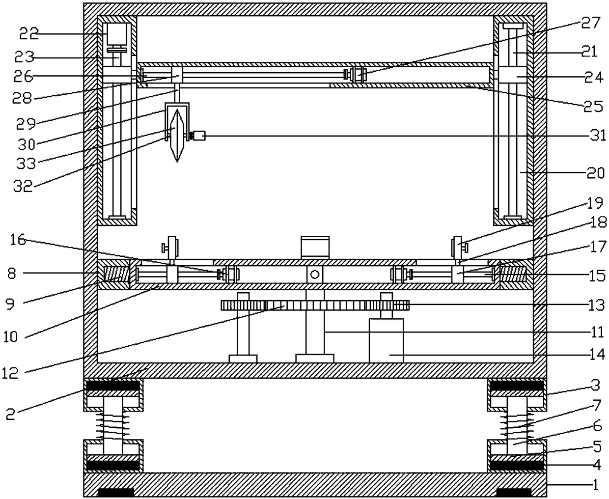
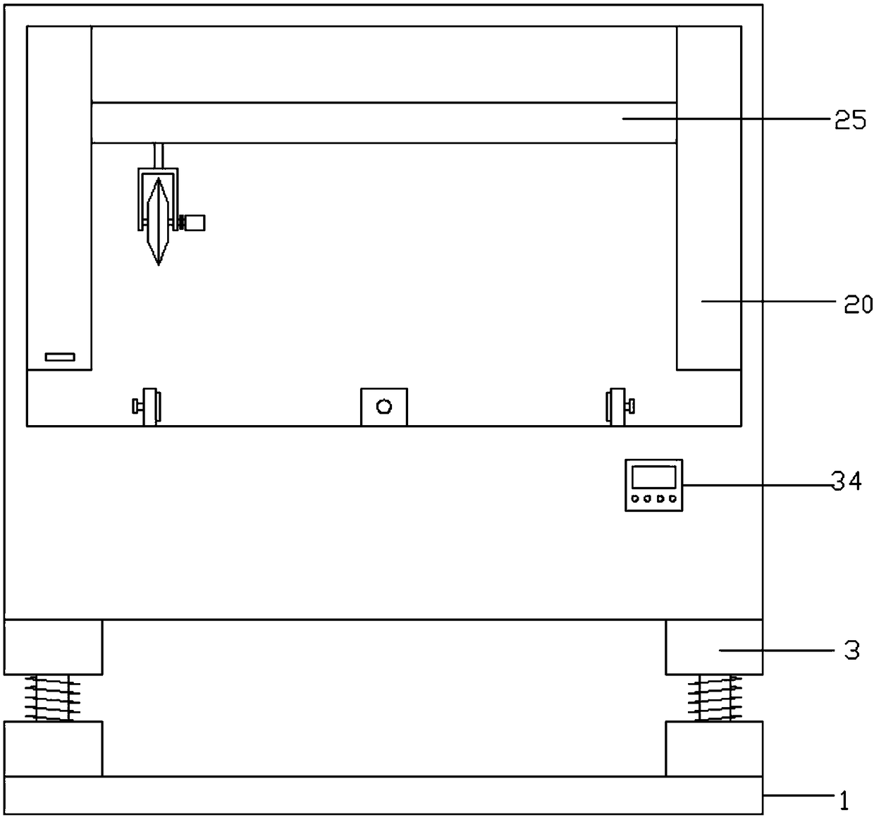
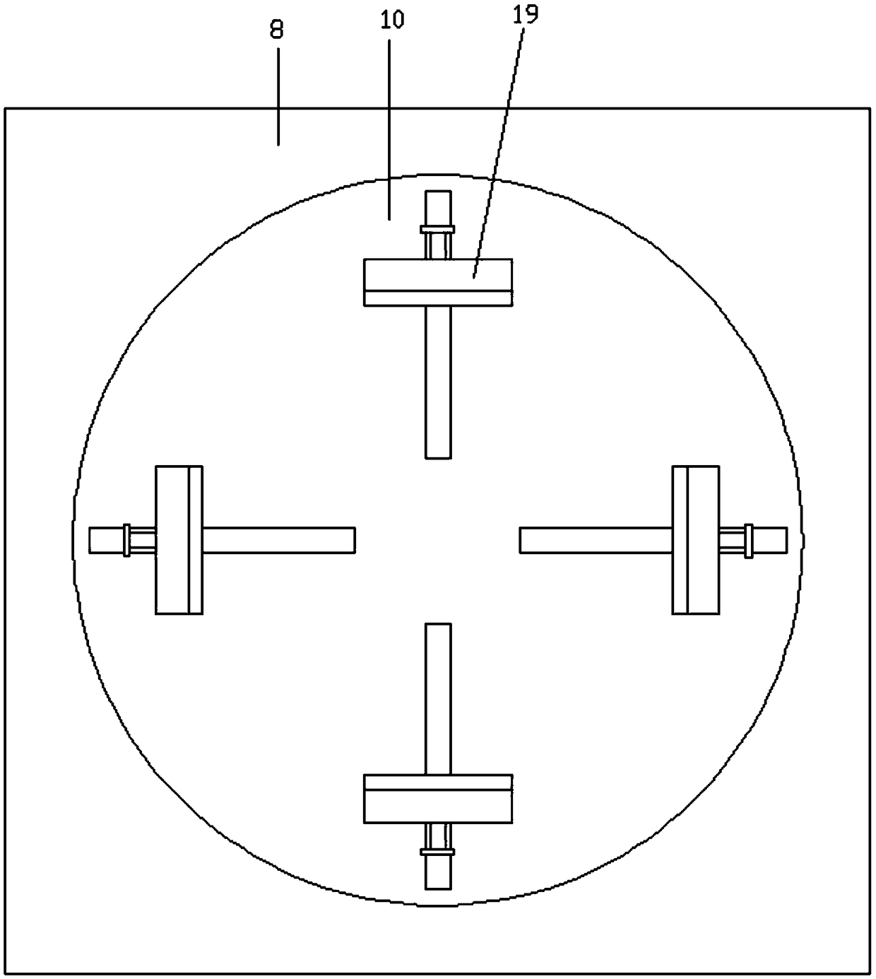
The invention discloses an efficient cutting device for composite material production and processing. The efficient cutting device comprises a bottom plate. A connecting frame is arranged above the bottom plate. A fixing groove is formed in the lower end inside the connecting frame. A rotating seat is arranged inside the fixing groove. First lead screws are arranged at four corners inside the rotating seat. A first sliding block is arranged on each first lead screw. A first connecting rod is arranged on the upper side of each first sliding block. A clamping plate is arranged on the upper sideof each first connecting rod. Sliding slots are correspondingly formed in the left and right sides of the upper end inside the connecting frame. A polished rod is arranged inside the sliding slot in the right end. A second lead screw is arranged inside the sliding slot in the left end. Second sliding blocks are correspondingly arranged on the second lead screw and the polished rod. A connecting plate is arranged on the inner side of each second sliding block. A third lead screw is arranged at the left end inside each connecting plate. A third sliding block is arranged on each third lead screw.A second connecting rod is arranged on the lower side of each third sliding block. A connecting cover is arranged on the lower side of each second connecting rod. A cutting disc is arranged inside each connecting cover. By the adoption of the efficient cutting device, composite materials can be effectively cut, so that the use of people can be facilitated, and the working efficiency of equipmentis improved.

Description

technical field [0001] The invention relates to the field of composite material production, in particular to a high-efficiency cutting device for composite material production and processing. Background technique [0002] Composite materials are multiphase materials prepared by compounding two or more materials such as metal materials, ceramic materials or polymer materials. Various materials learn from each other in terms of performance and produce synergistic effects. The performance is superior to the original constituent materials and meets various requirements. Composite materials consist of a matrix of continuous phases and phase reinforcement contained by the matrix. The base material is divided into metal and non-metal two categories. Commonly used metal substrates are aluminum, magnesium, copper, titanium and their alloys. Non-metallic substrates mainly include synthetic resin, graphite, rubber, ceramics, carbon, etc. Reinforcement materials mainly include glass...

Claims


Application Information

Patent Timeline
IPC IPC(8): B26D7/04B26D7/26B26D1/157
CPCB26D7/04B26D1/157B26D7/2635
Inventor 何苗
Owner 金寨县鑫和新能源科技有限公司
Features
  • Generate Ideas
  • Intellectual Property
  • Life Sciences
  • Materials
  • Tech Scout
  • Unparalleled Data Quality
  • Higher Quality Content
  • 60% Fewer Hallucinations
Learn More