

Automatic lip brick production system and production method of lip brick
A production system and lip brick technology, applied in the field of refractory material production, can solve the problems of low quality of lip bricks, achieve the effect of solving low quality, ultra-high degree of automation and operation stability, and improving work stability
- Summary
- Abstract
- Description
- Claims
- Application Information
AI Technical Summary
Problems solved by technology
Method used
Image

Examples
Embodiment 1
[0040] Embodiments of the present invention are described in detail below, examples of which are shown in the drawings, wherein the same or similar reference numerals designate the same or similar elements or elements having the same or similar functions throughout. The embodiments described below by referring to the figures are exemplary and are intended to explain the present invention and should not be construed as limiting the present invention.
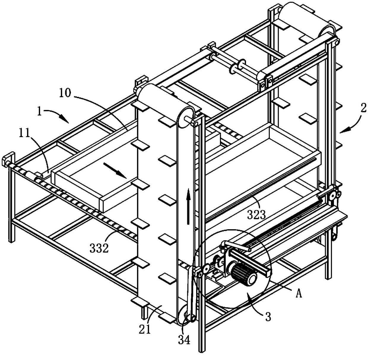
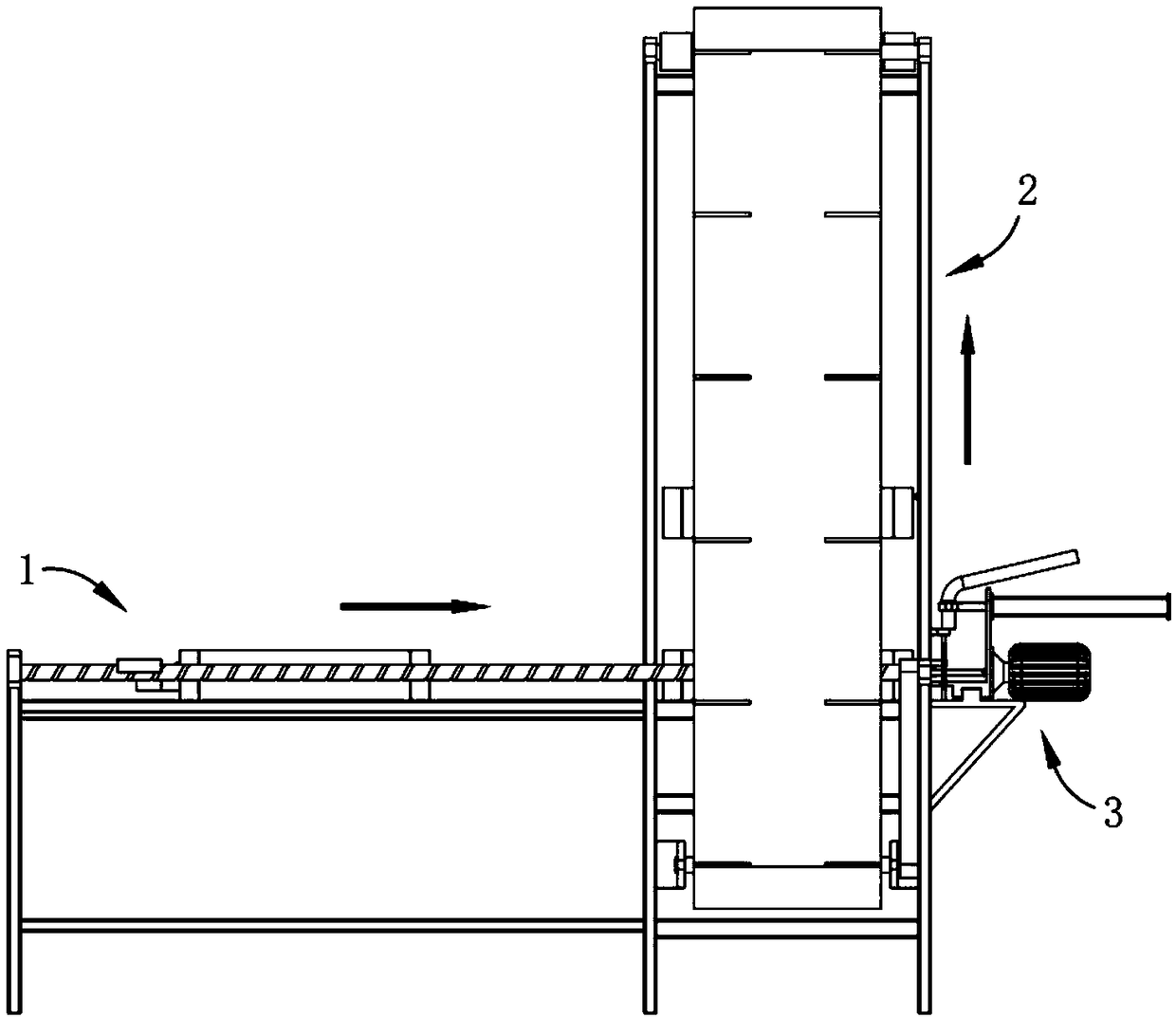
[0041] like figure 1 and 2 As shown, a lip brick automatic production system includes:
[0042] The transfer device A1 places the mold 10 on the feeding end of the transfer device A1, and drives the mold 10 to move through the transmission assembly 11 arranged on the transfer device A1;
[0043] Transfer device B2, after the mold 10 to be filled is transferred to the transfer device B2 through the transfer device A1, the filling device 3 fills the mixture into the mold 10 in a directional movement, and then the filling device 2...
Embodiment 2
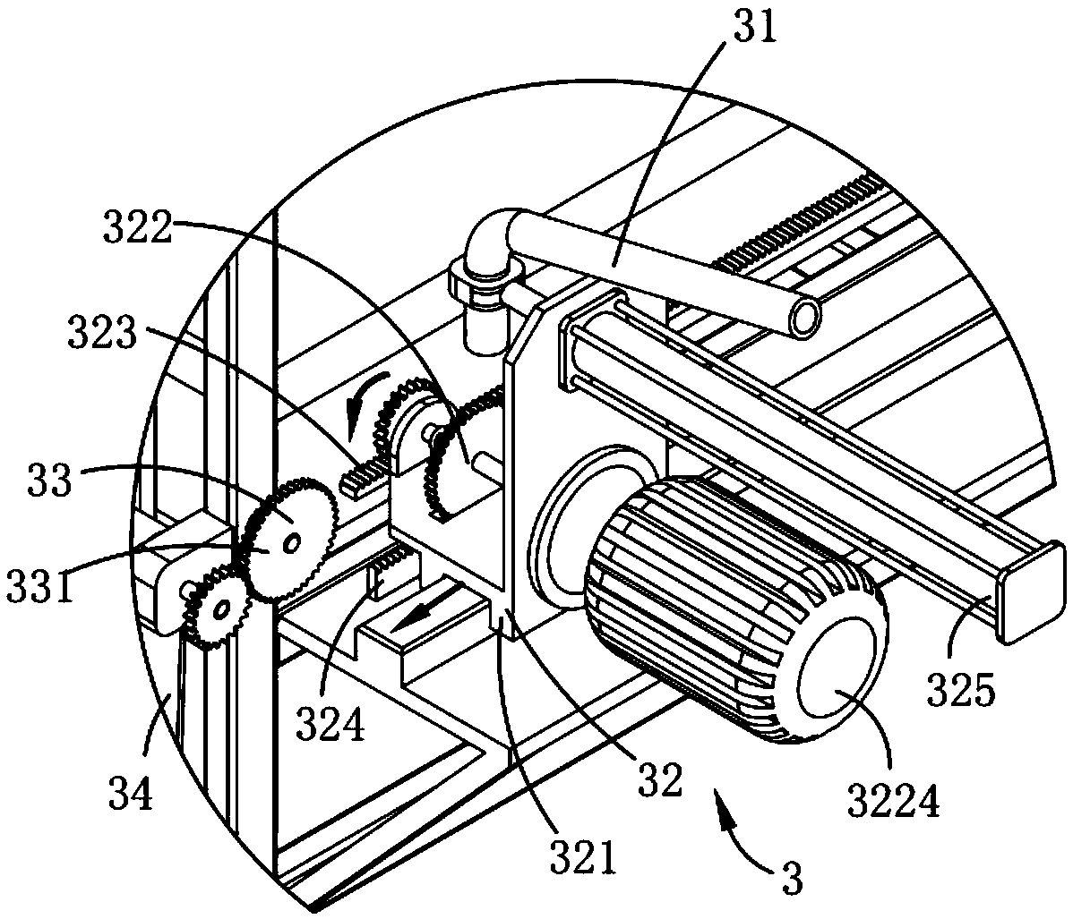
[0048] like figure 1 and 2 As shown, the parts that are the same as or corresponding to those in Embodiment 1 adopt the reference numerals corresponding to Embodiment 1. For the sake of simplicity, only the differences between Embodiment 1 and Embodiment 1 are described below; the differences between Embodiment 2 and Embodiment 1 The difference is that the moving assembly 32 includes a moving platform 321 slidably arranged along the length direction of the mold 10, a rotating part 322 arranged on the moving platform 321, and a rotating part 322 arranged on the mold 10 and connected with the rotating part. 322, the guide part 323 connected by transmission, and the rotating part 322 are connected by transmission, the receiving part 324 separating the guide part 323 from the rotating part 322 and the receiving part 324 arranged on the moving table 321 drive the reciprocating movement of the feeding pipe 31 The telescoping part 325; the rotating part 322 is driven by the motor to...
Embodiment 3
[0054] like figure 1 , 2 and 6, wherein the same or corresponding parts as in the second embodiment adopt the corresponding reference numerals with the second embodiment, for the sake of simplicity, only the difference between the second embodiment and the second embodiment is described below; the third embodiment and the first embodiment The difference is that: the first coupling assembly 33 includes a transmission gear 331 symmetrically rotatably mounted on the transfer device B2 and a transmission screw 332 connected to the transmission gear 331 in a gear pair transmission manner.
[0055] Further, as Image 6 As shown, the second coupling assembly 34 includes a reversing member a341 located on one side of the transfer device B2 and connecting the transmission screw 332 and the transmission assembly 21, and installed on the other side of the transfer device B2 to connect the transmission The gear 331 and the reversing member b342 of the transmission assembly 21, the rever...
PUM
 Abstract
Description
Claims
Application Information