Support foot plates and crane for mounting same

A technology of a foot plate and a crane, applied in the direction of a crane, etc., can solve the problems of difficulty, heavy weight, overall weight, single structure, etc., and achieve the effect of avoiding interference.

Active Publication Date: 2018-10-12
XUZHOU HEAVY MASCH CO LTD
View PDF10 Cites 1 Cited by
  • Summary
  • Abstract
  • Description
  • Claims
  • Application Information

AI Technical Summary

Problems solved by technology

[0007] 2) The existing foot plate is welded with a steel structure, and the weight is relatively heavy. It is difficult to adjust the two positions by manpower. Moreover, under the requirements of the lightweight structure of the whole machine, its overall weight and structural form are the key points that need to be improved. point

Method used


Image

  • Support foot plates and crane for mounting same
  • Support foot plates and crane for mounting same
  • Support foot plates and crane for mounting same

Examples


Embodiment Construction

[0033] In order to make the object, technical solution and advantages of the present invention clearer, the present invention will be further described in detail below. However, it should be understood that the specific embodiments described here are only used to explain the present invention, and are not intended to limit the scope of the present invention.

[0034] Unless otherwise defined, all technical terms and scientific terms used herein have the same meaning as commonly understood by those skilled in the technical field of the present invention, and the terms used in the description of the present invention herein are only to describe specific implementations The purpose of the example is not intended to limit the present invention.

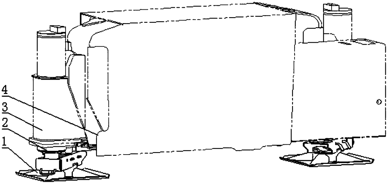
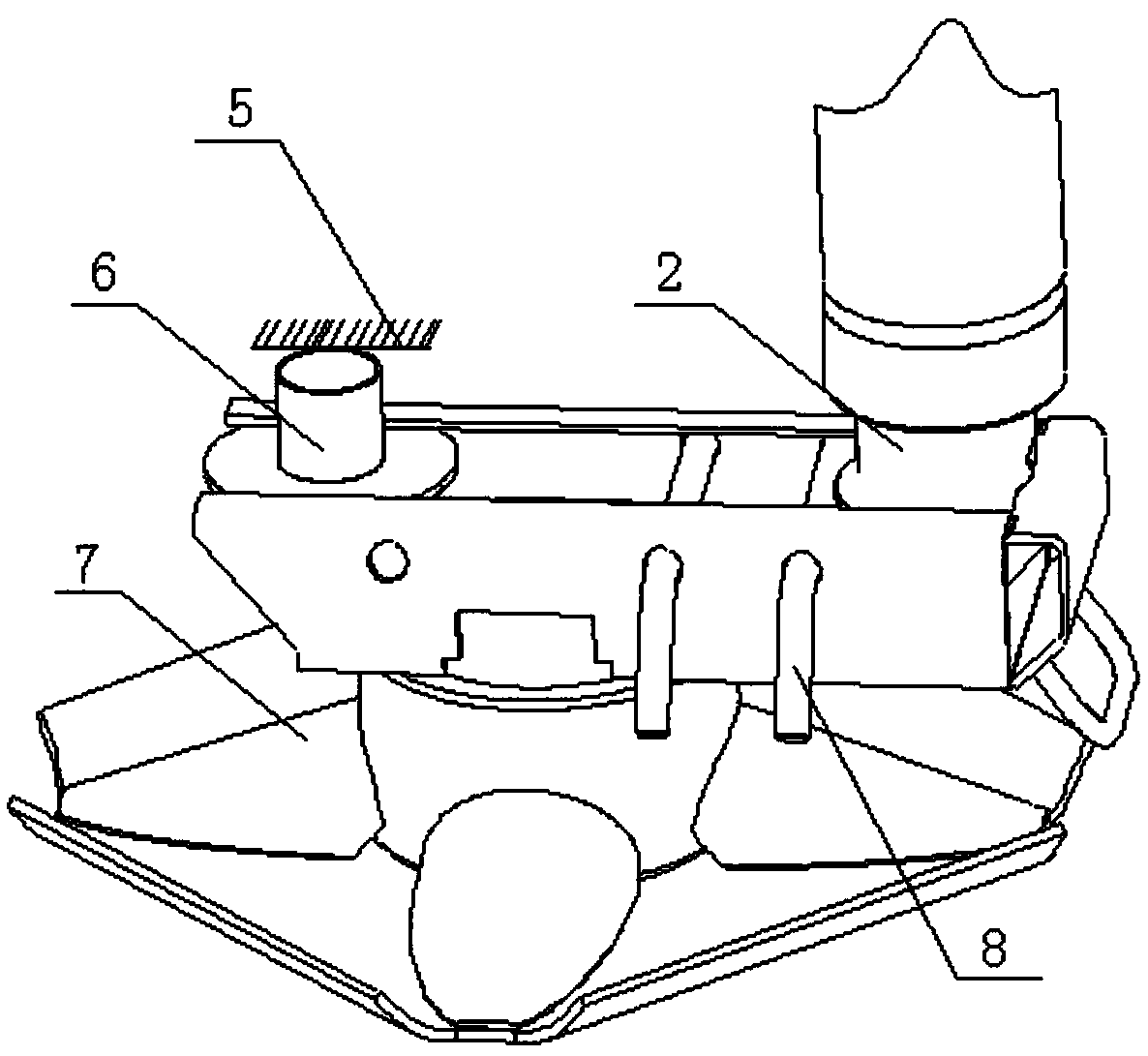
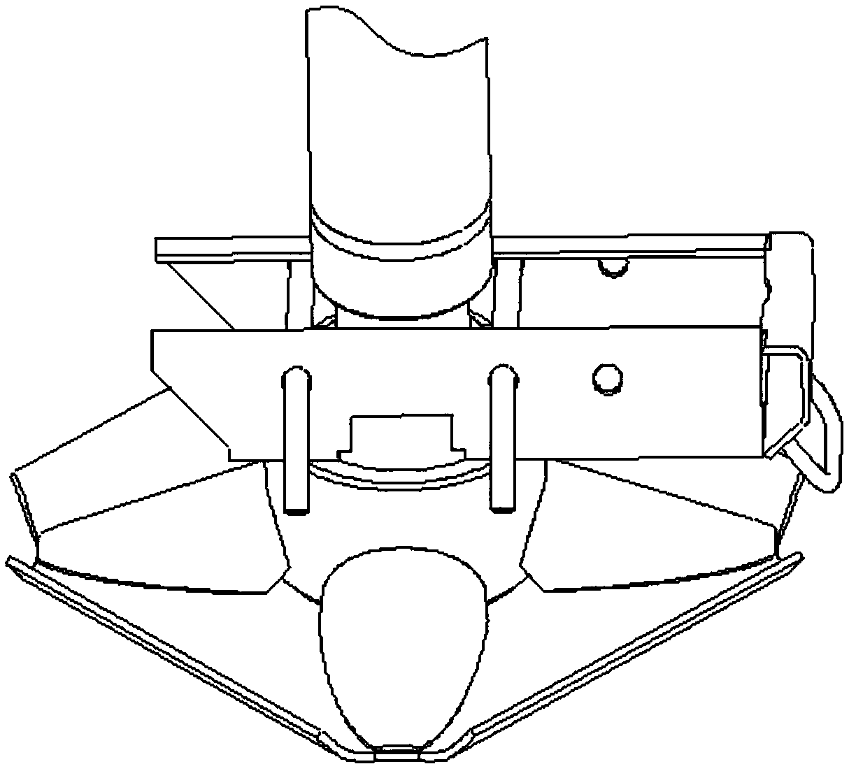
[0035] like Figure 5 , Image 6 and Figure 7 As shown, a foot plate, the foot plate 2 21 includes a guide groove 12, a support seat 13 for installing the guide groove 12, and a ball socket 14 arranged on the top of the support seat 1...


PUM


Abstract

The invention discloses support foot plates and a crane for mounting the support foot plates and belongs to the technical field of crane equipment. The second support foot plate comprises a guide slot, a support seat for mounting the guide slot and a ball socket arranged at the top of the support seat and used for mounting an oil cylinder ball head. A limiting groove is formed in the support seat.The ball socket is embedded into the limiting groove. The ball socket is in interference fit with the support seat. The guide slot adopts a non-linear structure and is provided with a hook limiting beam, a working hole position and a hanging hole position. When the oil cylinder ball head of a vertical oil cylinder is positioned in the ball socket, a fastening pin shaft is mounted in the working hole position to enable the second support foot plate to be in a working state. When the oil cylinder ball head of the vertical oil cylinder is disengaged from the ball socket, the fastening pin shaftis mounted in the hanging hole position to enable the second support foot plate to be in a non-working state. According to the support foot plate, the support seat of the support foot plate is manufactured by adopting an integrally formed structure, the material specific gravity of the support seat is lower than that of an existing steel structure, and the weight of the whole support foot plate structure can be greatly reduced compared with the steel welding structure.

Description

technical field [0001] The invention relates to a foot plate and a crane equipped with the foot plate, belonging to the technical field of crane equipment. Background technique [0002] The foot plate in the crane is a similar plate structure, which is used to support the crane in the lifting operation and transmit the force to the support surface, so as to play the role of bearing capacity and stable operation equipment. Generally, a crane has four foot plates, and the four foot plates are in contact with the support surface during the lifting operation to form a four-point support. [0003] The outrigger plate in the crane is generally installed at the end of the vertical cylinder of the outrigger, and moves with the movement of the vehicle and the vertical cylinder. There are mainly two types of foot plates used in cranes, one is the gland type; the other is the push-pull type, such as figure 1 As shown, the supporting leg plate one 1 is connected with the vertical oil ...

Claims


Application Information

Patent Timeline
Patent Type & Authority Applications(China)
IPC IPC(8): B66C23/80
CPCB66C23/80
Inventor 计海兵蒋静陈江伟王新强
Owner XUZHOU HEAVY MASCH CO LTD
Why Eureka
Try Eureka