
Fermenting tank for biological pharmacy

A bio-pharmaceutical and fermenter technology, applied in bioreactor/fermenter combination, specific-purpose bioreactor/fermenter, biomass post-processing, etc. problems such as low condensation efficiency, to achieve the effect of improving experience and facilitating observation

Inactive Publication Date: 2018-10-12
安吉艾格赛思生物科技有限公司
View PDF0 Cites 4 Cited by
  • Summary
  • Abstract
  • Description
  • Claims
  • Application Information

AI Technical Summary

Problems solved by technology

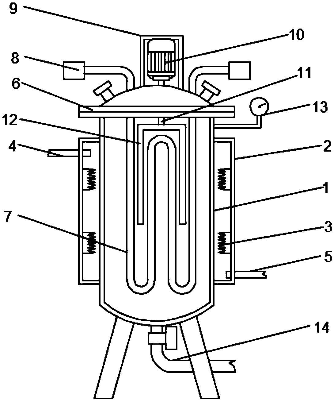
[0002] The fermenter is a device used for microbial fermentation. Generally, it needs to be strictly sterilized and easy to clean. In order to make the microbial fermentation more reasonable and rapid, it is necessary to keep warm or condense the fermenter to ensure the normal progress of the fermentation. However, the existing The heat preservation and condensation efficiency of the fermentation tank is relatively low, or there is a spiral condensation pipe for condensation, and the condensation efficiency is improved, but there is a certain dead angle in the condensation pipe, and the condensation pipe is fixed, so it is very difficult to clean the condensation pipe. It is inconvenient, and it is not convenient to clean the dead corners, which reduces the cleaning efficiency. Moreover, the interior of the fermenter is a closed space, and the fermentation situation cannot be directly observed from the outside, and it is not convenient to record the characteristics of the fermentation.

Method used


Image

  • Fermenting tank for biological pharmacy
  • Fermenting tank for biological pharmacy
  • Fermenting tank for biological pharmacy

Examples


Embodiment Construction

[0021] The following will clearly and completely describe the technical solutions in the embodiments of the present invention with reference to the accompanying drawings in the embodiments of the present invention. Obviously, the described embodiments are only some, not all, embodiments of the present invention. Based on the embodiments of the present invention, all other embodiments obtained by persons of ordinary skill in the art without making creative efforts belong to the protection scope of the present invention.

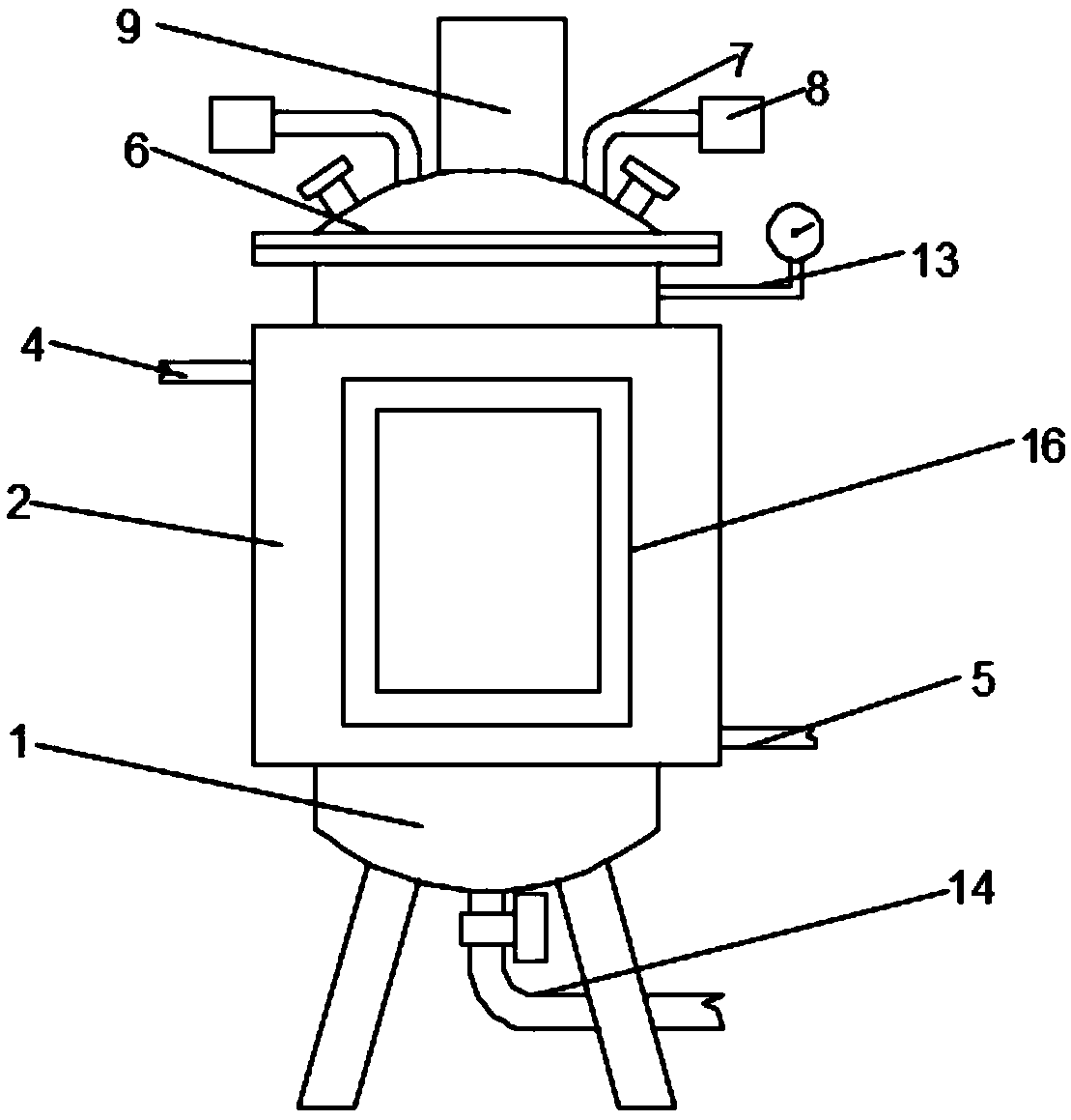
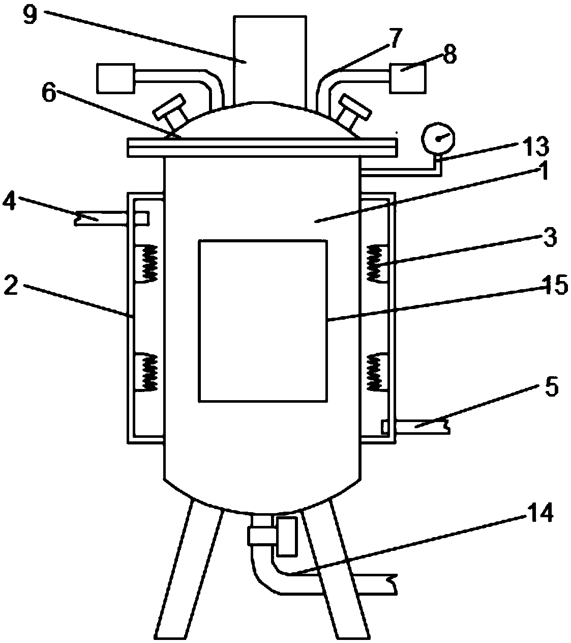
[0022] see Figure 1-3 , the present invention provides a technical solution: a fermenter for biopharmaceuticals, comprising a fermenter body 1, the upper end and the lower end of both sides of the outer wall of the fermenter body 1 are fixedly connected with a thermal insulation shell 2, and the upper end and the lower end of the inner wall of the thermal insulation shell 2 are fixedly connected to each other. The lower end is fixedly connected with a thermal...


PUM


Abstract

The invention discloses a fermenting tank for biological pharmacy, and relates to the technical field of biological pharmacy. The fermenting tank comprises a fermenting tank body, wherein the upper ends and lower ends of both sides of the outer wall of the fermenting tank body are fixedly connected with a heat insulation outer casing; the upper ends and lower ends of both sides of the inner wall of the heat insulation outer casing are fixedly connected with heat insulation heating wires; the upper end of one side of the outer wall of the heat insulation outer casing is fixedly connected with awater drain pipe; the lower end of one side, away from the water drain pipe, of the outer wall of the heat insulation outer casing is fixedly communicated with a water intake pipe; the top part of the fermenting tank body is fixedly connected with a top cover; a spiral condensing pipe is arranged on the fermenting tank body; both ends of the spiral condensing pipe respectively penetrate through the fermenting tank body, and extend out of the fermenting tank body; the two ends of the spiral condensing pipe are respectively fixedly connected with a pipeline connecting sleeve; the top part of the top cover is fixedly connected with a control box body. The fermenting tank for biological pharmacy has the advantages that the heat insulation and condensing efficiencies are high, the condensing pipe can be conveniently cleaned, and the fermenting condition can be conveniently observed.

Description

technical field [0001] The invention relates to the technical field of biopharmaceuticals, in particular to a fermenter for biopharmaceuticals. Background technique [0002] The fermenter is a device used for microbial fermentation. Generally, it needs to be strictly sterilized and easy to clean. In order to make the microbial fermentation more reasonable and rapid, it is necessary to keep warm or condense the fermenter to ensure the normal progress of the fermentation. However, the existing The heat preservation and condensation efficiency of the fermentation tank is relatively low, or there is a spiral condensation pipe for condensation, and the condensation efficiency is improved, but there is a certain dead angle in the condensation pipe, and the condensation pipe is fixed, so it is very difficult to clean the condensation pipe. It is inconvenient, and it is not convenient to clean the dead corners, which reduces the cleaning efficiency. Moreover, the interior of the fer...

Claims


Application Information

Patent Timeline
IPC IPC(8): C12M1/00C12M1/34C12M1/02
CPCC12M23/02C12M23/22C12M23/38C12M23/48C12M27/02C12M41/22C12M41/24
Inventor 邵明星
Owner 安吉艾格赛思生物科技有限公司
Learn More