
Automobile engine heat energy exchanger

A technology for heat energy exchangers and automobile engines, which is applied in the cooling of engine components, machines/engines, and engines, etc., can solve the problems of affecting the heat dissipation effect, blocking the heat dissipation pipes, and high production costs, so as to protect the heat energy exchanger and increase the service life. , the effect of reducing vibration

Inactive Publication Date: 2018-10-12
WEIFANG UNIVERSITY
View PDF8 Cites 3 Cited by
  • Summary
  • Abstract
  • Description
  • Claims
  • Application Information

AI Technical Summary

Problems solved by technology

[0003] Existing heat exchangers for automobile engines are usually divided into two types of heat dissipation and cooling methods, namely water cooling and air cooling. The normal output of the automobile engine is restricted. At the same time, the existing automobile engine heat exchanger has a large volume and a heavy weight, which does not meet the requirements of the current automobile production to reduce the weight of the automobile, and its structure is complex and the production cost is high. The traditional engine heat exchange Due to the quality of the coolant, scale and rust will accumulate inside the radiator. After a long time, it will easily block the heat dissipation pipe, affecting the heat dissipation effect, and need to be replaced frequently

Method used


Image

  • Automobile engine heat energy exchanger
  • Automobile engine heat energy exchanger
  • Automobile engine heat energy exchanger

Examples


Embodiment Construction

[0022] The following will clearly and completely describe the technical solutions in the embodiments of the present invention with reference to the accompanying drawings in the embodiments of the present invention. Obviously, the described embodiments are only some, not all, embodiments of the present invention. Based on the embodiments of the present invention, all other embodiments obtained by persons of ordinary skill in the art without making creative efforts belong to the protection scope of the present invention.

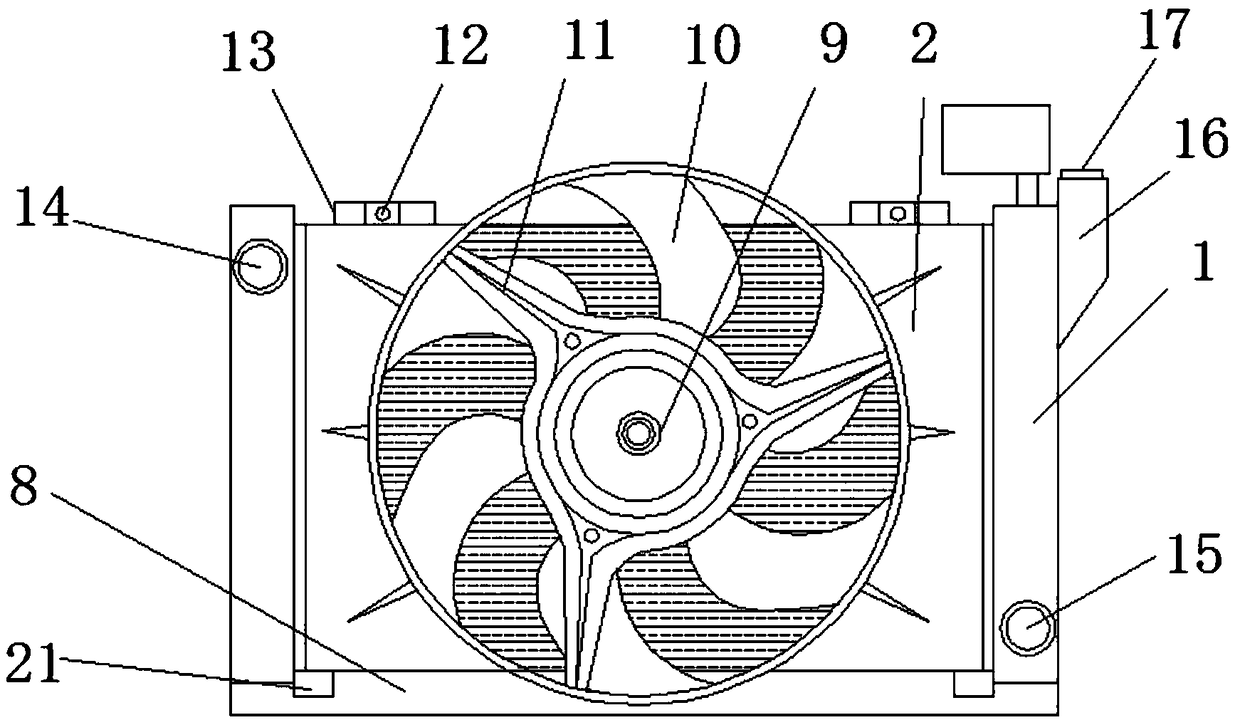
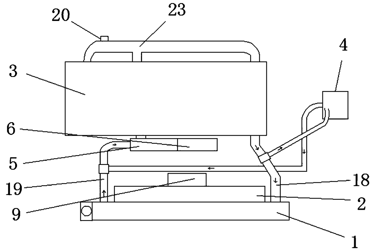
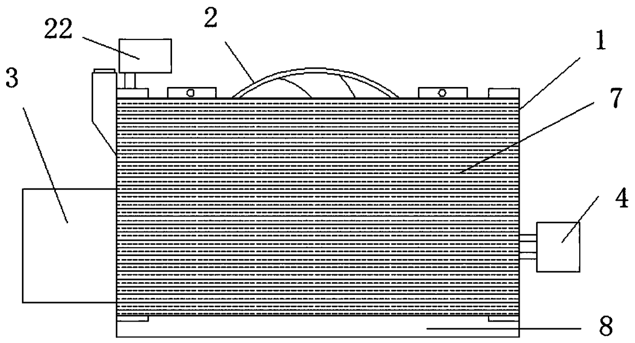
[0023] see Figure 1-3 The present invention provides a technical solution: a heat exchanger for an automobile engine, comprising a heat exchanger body 1, an electric fan 2, an engine 3, a liquid storage tank 4, a thermostat 5, a water pump 6 and a cleaning agent storage tank 22, The front side of the heat exchanger body 1 is provided with a radiator core 7, the bottom side is provided with a base 8, and fixed frames 13 are arranged symmetrically at both ends ...


PUM


Abstract

The invention discloses an automobile engine heat energy exchanger. The automobile engine heat energy exchanger comprises a heat energy exchanger body, a motor fan, an engine, a liquid storage pot, athermostat, a water pump and a cleaning agent storage tank; a radiator core is arranged on the right side of the heat energy exchanger body; a base is arranged on the bottom side; fixing frames are symmetrically arranged at the two ends of the upper side; a water filling chamber is formed in the upper end of the left side of the heat energy exchanger body; a water box cover is arranged on the upper side of the water filling chamber; the motor fan is arranged at the middle part of the back of the heat energy exchanger body; a water inlet is formed in the part above the left side of the back ofthe heat energy exchanger body; a water outlet is formed in the part below the right side; an engine water inflow pipe, an engine water outflow pipe and a water circulation pipe are arranged on the engine; the engine water inflow pipe is connected with the water outlet in the heat energy exchanger body; and the engine water outflow pipe is connected with the water inlet in the heat energy exchanger body. With the adoption of a water-cooling and air-cooling double-layer radiating mode, the radiating property of the heat energy exchanger is good; and with the adoption of the cleaning agent storage tank, cleaning is facilitated further, and the service life of the heat energy exchanger is prolonged.

Description

technical field [0001] The invention relates to the technical field of heat exchangers, in particular to an automobile engine heat exchanger. Background technique [0002] A heat exchanger (also known as a heat exchanger or heat exchange equipment) is a device used to transfer heat from a hot fluid to a cold fluid to meet the specified process requirements. It is an industrial application of convective heat transfer and heat transfer. It is widely used in automobiles and construction machinery vehicles. Every car will be equipped with at least one radiator; most cars and passenger cars will be installed with air conditioning units; supercharged diesel engines that meet Euro II emission regulations are equipped with an oil cooler, and cars with automatic transmissions must be installed with an oil cooler. Cooler: Intercoolers are installed in heavy trucks, large passenger cars, some medium and light passenger cars and trucks in order to meet emission standards. There are ma...

Claims


Application Information

Patent Timeline
Patent Type & Authority Applications(China)
IPC IPC(8): F01P3/18F01P7/16F01P11/06F01P11/00
CPCF01P11/00F01P3/18F01P7/16F01P11/06F01P2007/168F01P2011/063
Inventor 马成习郭姗姗
Owner WEIFANG UNIVERSITY
Learn More