Anti-silt turbulent vane guide wheel and turbulent pump based on the turbulent vane guide wheel

A turbulent flow and guide wheel technology, applied in the field of turbulent flow pumps, can solve the problems of insufficient production binding capacity of electric pump design manufacturers, difficulty in the design of the vane guide wheel to meet the use requirements, and increase the rotational resistance of the vane guide wheel bearings, etc., to achieve stability and high efficiency Oil production, reduce the probability of plugging, and increase the effect of mud and sand activities

Active Publication Date: 2019-09-20
CHINA NAT OFFSHORE OIL CORP +1
View PDF7 Cites 0 Cited by
  • Summary
  • Abstract
  • Description
  • Claims
  • Application Information

AI Technical Summary

Problems solved by technology

In the application process of electric submersible pumps, due to special well conditions such as sand and mud in oil wells, it is easy to cause failures such as production decline, gradually increasing operating current, pump jamming, overload shutdown, and pump shaft fracture. According to statistics, the cause of the failure is mostly due to the deposition of sand and dirt in the vane guide wheel of the submersible oil pump during the operation of the submersible oil pump or after the pump is manually stopped, which increases the rotational resistance of the vane guide wheel bearing and forms a blockage in the pump flow channel , especially at the pump outlet and inlet
[0003] With the continuous improvement of oilfield injection and production systems, there are more or less sand and mud in the production of oil wells. The current design of the vane guide wheel is based on the anti-sanding material of the bearing, the ability of sand settling, and the widening of the flow channel. However, it has not been able to completely solve the problems of mud deposits and blockage of the vane guide wheel flow channel. In the annual statistics of pump failure inspections, 5% of the pump inspections are still caused by such well conditions. However, the electric pump design manufacturers and the actual production Insufficient binding capacity makes it difficult for the current conventional vane guide wheel design to meet the requirements of sand and mud well conditions. It is necessary to develop a mud-sand turbulent flow vane guide wheel from the design source

Method used


Image

  • Anti-silt turbulent vane guide wheel and turbulent pump based on the turbulent vane guide wheel
  • Anti-silt turbulent vane guide wheel and turbulent pump based on the turbulent vane guide wheel
  • Anti-silt turbulent vane guide wheel and turbulent pump based on the turbulent vane guide wheel

Examples


Embodiment Construction

[0024] In order to further understand the content, characteristics and effects of the present invention, the following examples are given, and detailed descriptions are as follows in conjunction with the accompanying drawings:

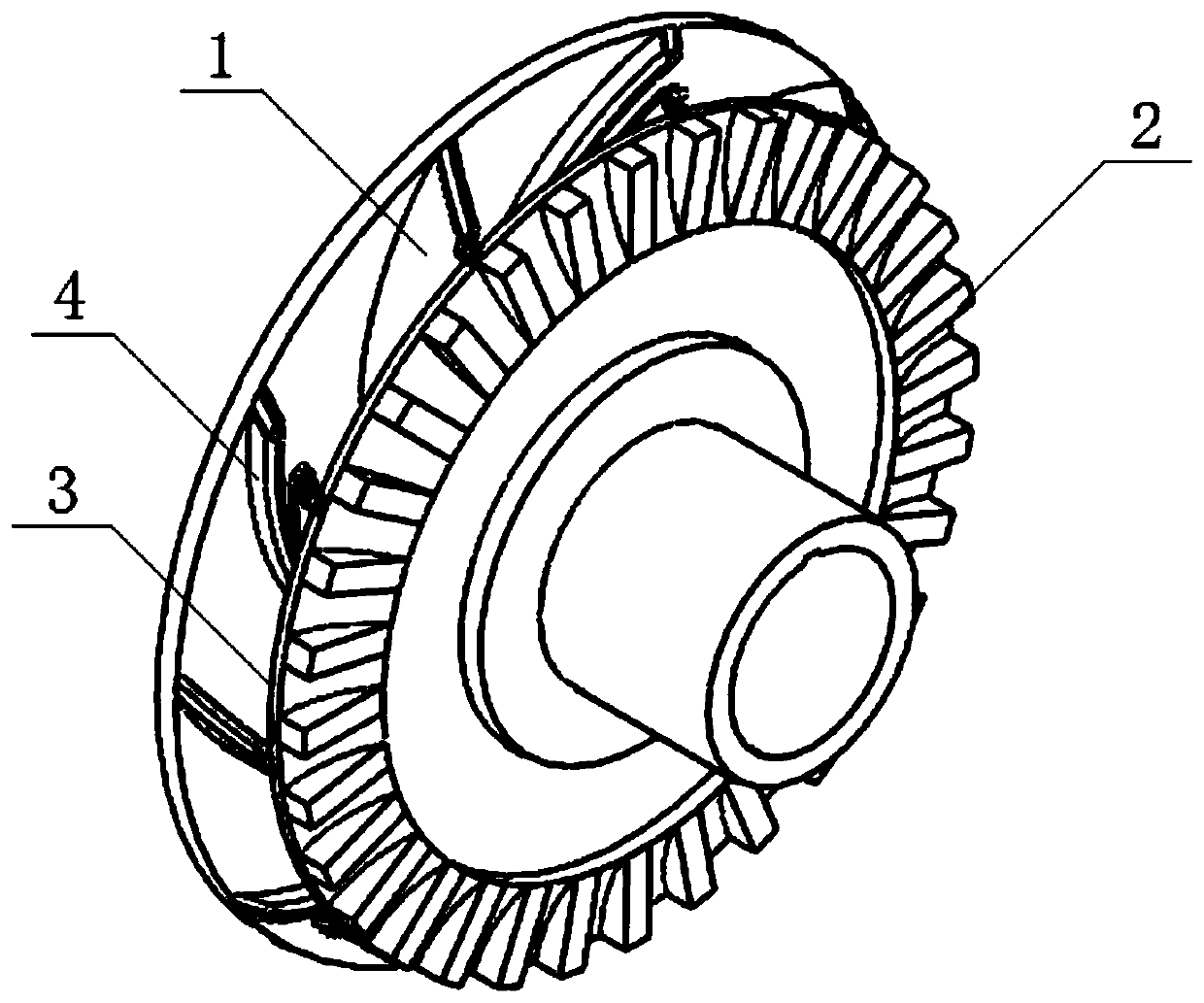
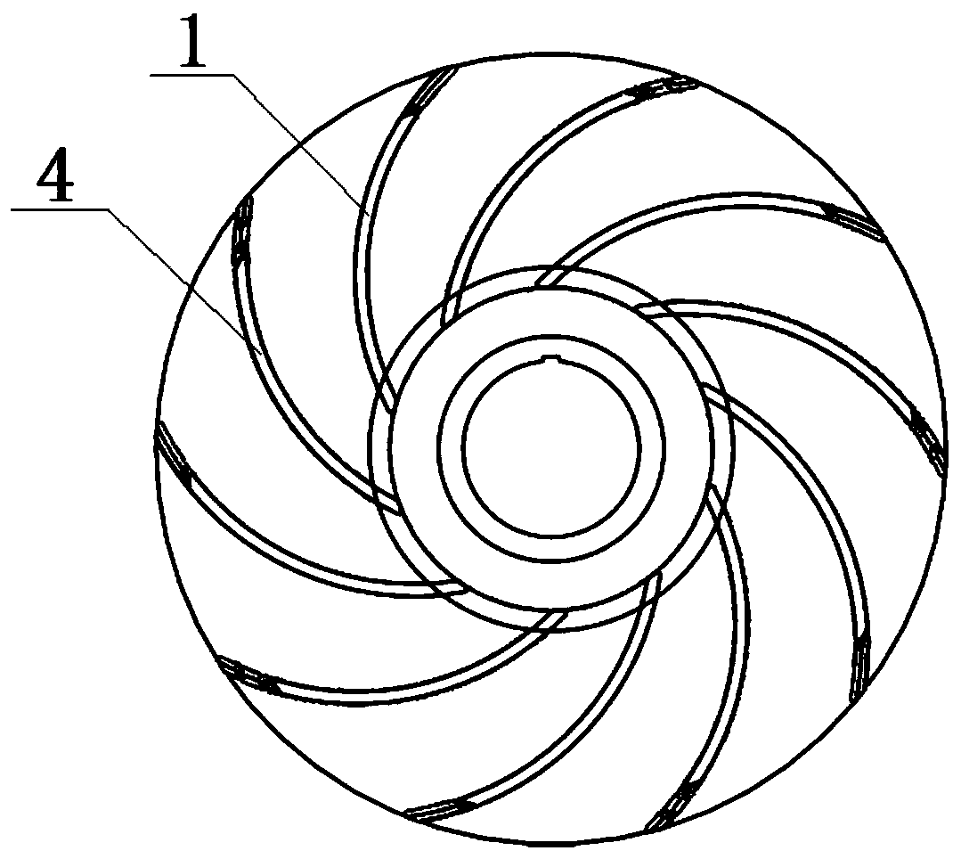
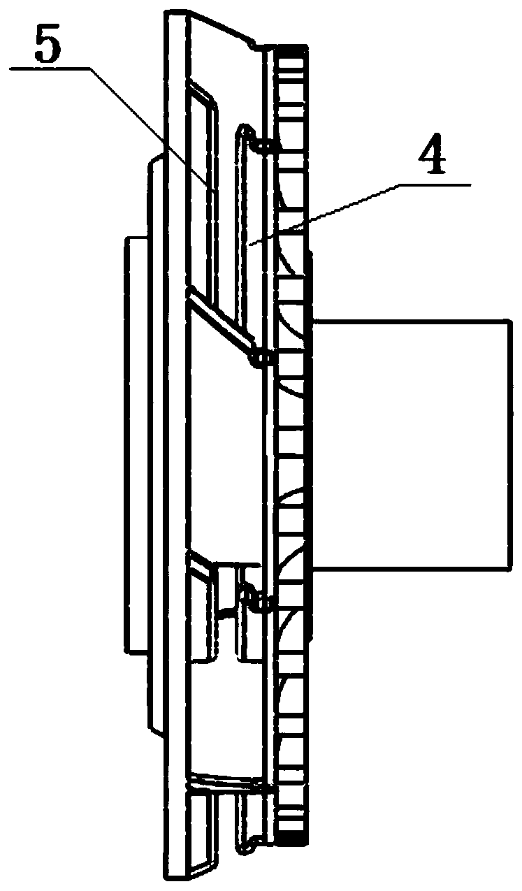
[0025] like Figure 1 to Figure 6 As shown, this embodiment provides a mud-sand turbulent-flow vane guide wheel, which is assembled by a single-stage impeller 6 and a single-stage guide casing 7. The single-stage impeller 6 is innovatively designed as a turbulent impeller on the basis of a conventional centrifugal impeller, and the turbulent flow The outer diameter of the impeller is the same as that of the conventional impeller with the same displacement. The turbulent impeller rotates inside the single-stage guide housing 7 to form a single-stage turbulent vane guide wheel. The single-stage turbulent vane guide wheels are respectively installed at the outlet 8 of the single-section pump and the inlet 9 of the single-section pump to form a turbulent ...


PUM


Abstract

The invention belongs to the technical field of electric submersible pumps and discloses a silt-preventing turbulence guide impeller and a turbulence pump based on the turbulence guide impeller. A single-level impeller of the silt-preventing turbulence guide impeller comprises lifting blades and turbulence blades which are arranged alternatively and distributed uniformly. A cut opening extending to the edge of the outer end from the root portion of each turbulence blade is arranged in the middle of each turbulence blade. Meanwhile, rectangular wheel teeth uniformly distributed in the radial direction are arranged on the ring face of the outer ring of an impeller cover plate, wherein the thicknesses of the rectangular wheel teeth are equal. Turbulence guide impellers of a certain proportionare installed on a single-section pump outlet and a single-section pump inlet of a submersible pump to form a turbulence pump. According to the turbulence guide impeller, by changing the flowing state of fluid media in a pump inner liquid channel, deposition of silt is reduced, thus the blocking possibility of the electric submersible pump is reduced, and stable and efficient oil extraction production is achieved under multiple well conditions of proper silt discharging and high oil mud and asphaltene content.

Description

technical field [0001] The invention belongs to the technical field of electric submersible pumps, and in particular relates to a mud-sand-proof turbulent vane guide wheel and a turbulent pump based on the turbulent vane guide wheel. Background technique [0002] At least 85% of the mechanical production wells in my country's offshore oil fields rely on electric submersible pumps for lifting, and their production contribution reaches more than 90%. In the application process of electric submersible pumps, due to special well conditions such as sand and mud in oil wells, it is easy to cause failures such as production decline, gradually increasing operating current, pump jamming, overload shutdown, and pump shaft fracture. According to statistics, the cause of the failure is mostly due to the deposition of sand and dirt in the vane guide wheel of the submersible oil pump during the operation of the submersible oil pump or after the pump is manually stopped, which increases th...

Claims


Application Information

Patent Timeline
Patent Type & Authority Patents(China)
IPC IPC(8): F04D29/22F04D29/24
Inventor 张光一付军石平太黄新春
Owner CHINA NAT OFFSHORE OIL CORP
Why Eureka
Try Eureka