Pipe damping device

A vibration damping device and pipeline technology, which is applied to pipeline brackets, circuit devices, battery circuit devices, etc., can solve problems such as pipeline vibration, tube damage, easy loosening of brackets, etc., and achieve the effect of convenient maintenance

Inactive Publication Date: 2018-10-12
ZHEJIANG OCEAN UNIV
View PDF10 Cites 15 Cited by
  • Summary
  • Abstract
  • Description
  • Claims
  • Application Information

AI Technical Summary

Problems solved by technology

[0002] Pipeline transportation is widely used in electric power, petroleum and other industries. The liquid in the pipeline has pressure pulsation, which is easy to cause severe vibration of the pipeline. Long-term vibration of the pipeline is likely to cause damage to the pipeline and water ingress. If the oil pipeline is

Method used


Image

  • Pipe damping device
  • Pipe damping device
  • Pipe damping device

Examples


Embodiment 1

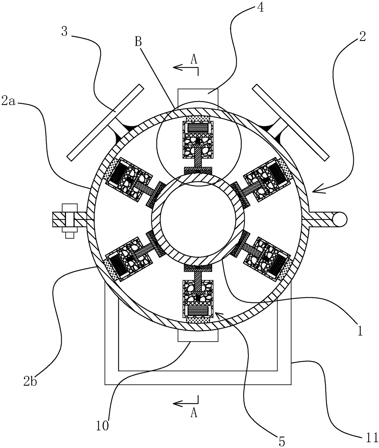
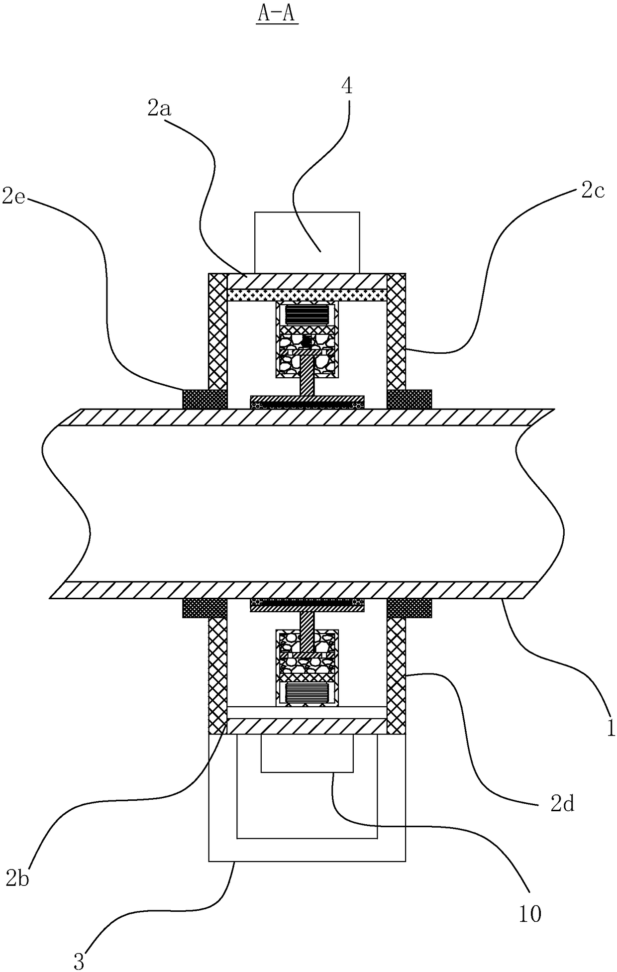
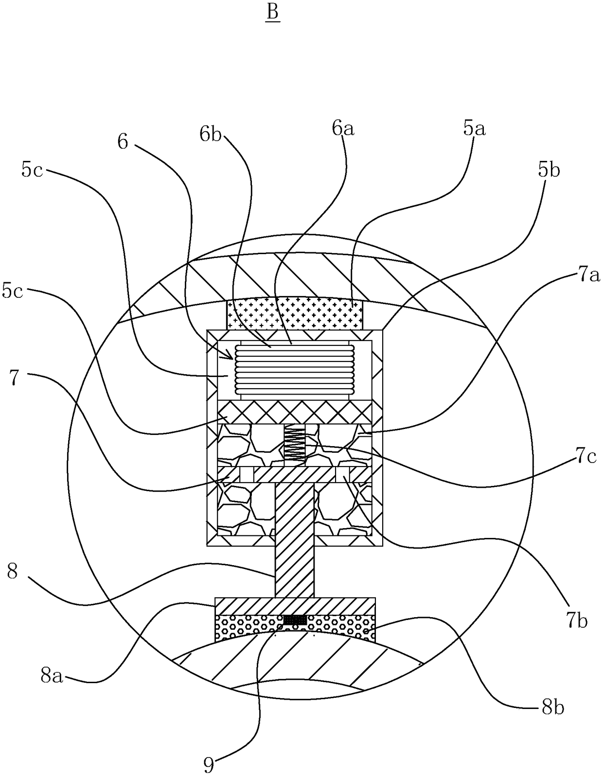
[0027] Such as Figures 1 to 3 As shown, a pipeline damping device includes a housing 2 and a base 11, the housing 2 is a tubular structure, the pipe 1 passes through the middle of the housing 2, and the housing 2 is arranged on the base 11, The inner wall of the housing 2 is provided with several damping mechanisms 5 in the circumferential direction. The damping mechanism 5 includes a cylinder 5b and a piston rod 8. A baffle 5c is arranged inside the cylinder 5b. The baffle 5c The cylinder 5b is divided into a cavity 5c and a buffer chamber 7a, the cavity 5c is provided with an electromagnet 6, the buffer chamber 7a is provided with magnetorheological fluid, and one end of the piston rod 8 is located in the cylinder 5b Inside and the end is fixedly connected with a piston 7, the other end of the piston rod 8 is located outside the cylinder body 5b and the end is fixedly connected with a fixed plate 8a, the piston 7 is provided with several through holes 7b, the piston 7 Slid...

Embodiment 2

[0040] The second embodiment is basically the same as the first embodiment, the difference is that, as Figure 4 As shown, the solar power generation device is replaced by the ocean current power generation device, so that the vibration reduction device can be applied to the underwater environment. The ocean current power generation device includes a generator 12, and the generator 12 is arranged on the semicircular pipe-2a through a bracket 14, so that The end of the input shaft of the generator 12 is provided with an impeller 13, and the ocean current on the seabed drives the impeller 13 to rotate to make the generator 12 generate electricity, which is then stored in the storage battery 4 to provide electric energy to the electromagnet 6 to change the magnetorheological fluid in the buffer chamber 7a. Fluid resistance to realize the damping function of the pipe 1.


PUM


Abstract

The invention provides a pipe damping device, and belongs to the technical field of pipe equipment. The pipe damping device comprises a shell and a base; the shell is arranged on the base; multiple damping mechanisms are arranged in the peripheral direction of the inner side wall of the shell; the damping mechanisms comprise cylinder blocks and piston rods; baffle plates are arranged in the cylinder blocks for dividing the cylinder blocks into cavities and buffer cavities; electromagnets are arranged in the cavities; magnetorheological fluid is arranged in the buffer cavities; one ends of thepiston rods are positioned in the cylinder blocks, and the end parts are fixedly connected with pistons; the other ends of the piston rods are positioned out of the cylinder blocks, and the end partsare fixedly connected with fixed plates; multiple through holes are formed in the pistons; the pistons are slidingly arranged in the buffer cavities; return springs are arranged in the buffer cavities; one ends of the cylinder blocks are fixedly connected with the inner side wall of the shell through fixed bases; and the fixed plates are provided with induction mechanisms capable of controlling opening and closing of the electromagnets and the magnetic field intensity according to the magnitude of pipe vibration strength. The pipe damping device is simple in structure, and can adjust the buffer strength according to the pipe vibration strength to achieve flexible damping effect.

Description

technical field [0001] The invention belongs to the technical field of pipeline equipment and relates to a pipeline damping device. Background technique [0002] Pipeline transportation is widely used in electric power, petroleum and other industries. The liquid in the pipeline has pressure pulsation, which is easy to cause severe vibration of the pipeline. Long-term vibration of the pipeline is likely to cause damage to the pipeline and water ingress. If the oil pipeline is damaged, crude oil will leak and pollute the marine environment. . At present, rigid fasteners such as pipe brackets are used to prevent pipe vibration, but due to the long-term vibration, the brackets are easy to loosen, and the loose brackets will rigidly collide with the pipes, causing damage to the pipes. Contents of the invention [0003] The object of the present invention is to provide a pipe damping device with simple structure and good damping effect in view of the above-mentioned problems in...

Claims


Application Information

Patent Timeline
IPC IPC(8): F16L3/10F16F15/027F16F15/04H02J7/35
CPCF16F15/022F16F15/027F16F15/04F16L3/1075H02J7/35
Inventor 郭静史晓敏
Owner ZHEJIANG OCEAN UNIV
Why Eureka
Try Eureka