Vibration test device

A testing device and vibration table technology, which is used in measurement devices, vibration testing, and testing of machine/structural components, etc., can solve the problems of large size of seismic testing instruments, unsuitable measuring instruments, and complex structures, and achieve adjustable vibration intensity. , the effect of shortened life and strong safety performance

Inactive Publication Date: 2018-10-12
ZHENGZHOU JIZHI TECH CO LTD
View PDF0 Cites 4 Cited by
  • Summary
  • Abstract
  • Description
  • Claims
  • Application Information

AI Technical Summary

Problems solved by technology

[0004] The purpose of the present invention is: in order to solve the problem that the existing anti-seismic testing instruments are too large in size and too complicated in structure to be suitable for small precision instruments such as measuring instruments, the present invention provides a vibration testing device

Method used


Image

  • Vibration test device
  • Vibration test device
  • Vibration test device

Examples


Embodiment 1

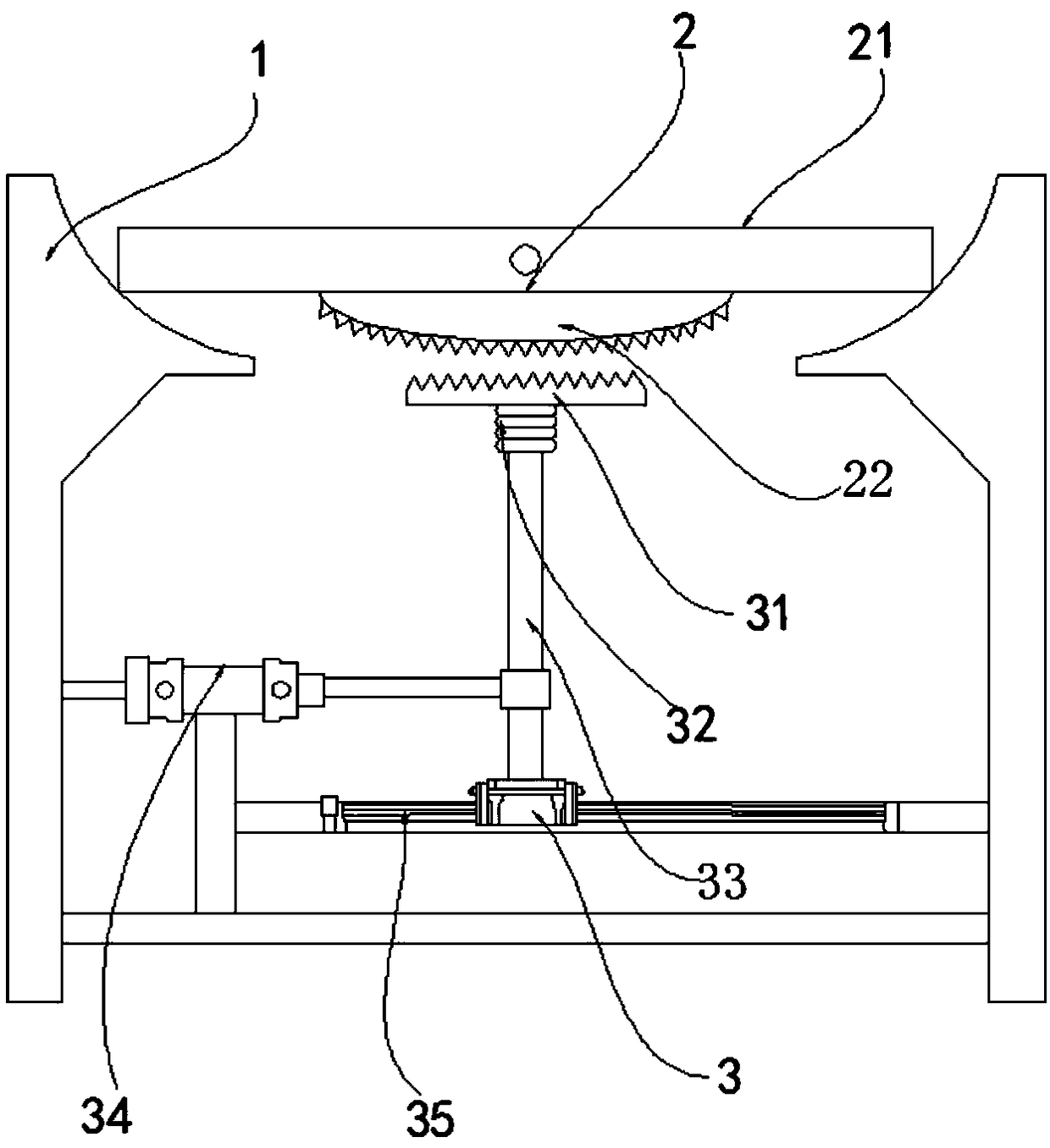
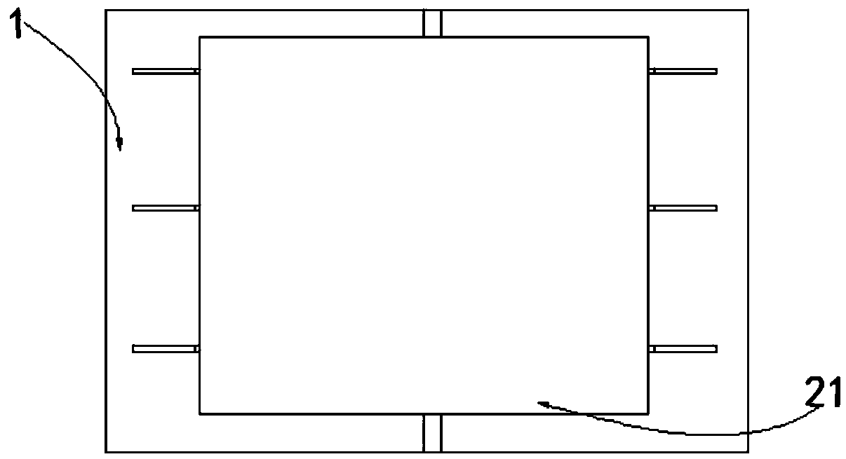
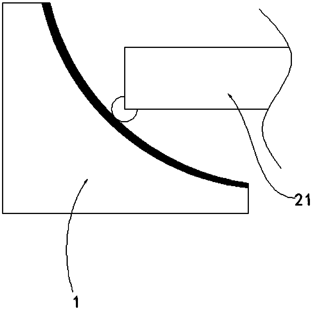
[0021] A vibration testing device, comprising a frame 1, a passive mechanism 2, and an active mechanism 3, the passive mechanism 2 is placed on the upper end of the frame 1, the passive mechanism 2 is connected to the lower end of the frame 1, and the active mechanism 3 is connected to the passive mechanism 3. The bottom of mechanism 2 cooperates by gear; Described driving mechanism 3 comprises spur rack 31, multi-layer damping ring 32, vertical bar 33, pushes cylinder 34 and slide bar 35, and the lower surface of described spur rack 31 is provided with multiple Layer shock absorbing ring 32, described multilayer shock absorbing ring 32 is positioned at the top of vertical bar 33, and described vertical bar 33 is connected with slide bar 35 and is used as the slide block of slide bar 35, and described vertical bar 33 and pushing cylinder 34 The piston rod is connected; the passive mechanism 2 includes a vibration table 21 and a vibration gear 22, the vibration gear 22 is connec...

Embodiment 2

[0027] A vibration testing device, comprising a frame 1, a passive mechanism 2, and an active mechanism 3, the passive mechanism 2 is placed on the upper end of the frame 1, the passive mechanism 2 is connected to the lower end of the frame 1, and the active mechanism 3 is connected to the passive mechanism 3. The bottom of mechanism 2 cooperates by gear; Described driving mechanism 3 comprises spur rack 31, multi-layer damping ring 32, vertical bar 33, pushes cylinder 34 and slide bar 35, and the lower surface of described spur rack 31 is provided with multiple Layer shock absorbing ring 32, described multilayer shock absorbing ring 32 is positioned at the top of vertical bar 33, and described vertical bar 33 is connected with slide bar 35 and is used as the slide block of slide bar 35, and described vertical bar 33 and pushing cylinder 34 The piston rod is connected; the passive mechanism 2 includes a vibration table 21 and a vibration gear 22, the vibration gear 22 is connec...


PUM


Abstract

The invention discloses a vibration test device,and relates to the field of anti-vibration detection. The vibration test device comprises a rack,a driven mechanism and a driving mechanism; the drivenmechanism comprises a vibration table and a vibration gear; the driving mechanism comprises a spur rack,a vertical bar,a push air cylinder and a slide bar,the slide bar and the push air cylinder are connected with the rack,the vertical bar is connected with the slide bar in a slide block form,a piston of the push air cylinder is connected with the vertical bar,and multiple layers of vibration reduction rings are arranged on the lower surface of the spur rack and located at the top end of the vertical bar; the vibration table is placed on the upper side of the rack,and the lower surface of thevibration table is provided with the vibration gear matched with the spur rack. The vibration test device has the advantages of being high in vibration efficiency,adjustable in vibration intensity andlong in service life.

Description

technical field [0001] The invention relates to the field of anti-seismic detection, in particular to an anti-seismic detection device for small instruments. Background technique [0002] As a big country in infrastructure construction, our country has infrastructure projects blooming all over the country. The three giants of infrastructure "roads, bridges, and tunnels" are marching into remote areas, deep mountains and old forests. The first step of all infrastructure projects is on-site measurement, so the environment for the use of precision measuring instruments is more complicated. Before reaching the measuring point, the measuring instrument will inevitably go through various vibrations and collisions to reach the measuring point. Therefore, the seismic testing of precision instruments is a must. However, the volume of existing anti-seismic testing instruments is too large, and the structure is too complex, which is not suitable for small precision instruments such a...

Claims


Application Information

Patent Timeline
IPC IPC(8): G01D18/00G01M7/02
CPCG01D18/00G01M7/022G01M7/027
Inventor 郭小波
Owner ZHENGZHOU JIZHI TECH CO LTD
Why Eureka
Try Eureka