
Heat-resistant visual liquid position display device

A display device and high-temperature-resistant technology, which is applied in the directions of lubrication indicator devices, measuring devices, liquid level indicators, etc., can solve the problems of material waste, unfavorable accurate observation, etc., and achieve the advantages of convenient manufacture, convenient operation, and reduced use and maintenance costs Effect

Pending Publication Date: 2018-10-12
ZHEJIANG YINLUN MACHINERY
View PDF0 Cites 1 Cited by
  • Summary
  • Abstract
  • Description
  • Claims
  • Application Information

AI Technical Summary

Problems solved by technology

The liquid level display device with this structure has a rectangular parallelepiped structure to facilitate connection with the liquid storage device. Since the overall rectangular parallelepiped structure is adopted, and the internal liquid guide is usually a circular tube structure, the thickness of different positions is different, which brings visual differences. conducive to accurate observation
At the same time, it will cause material waste
[0004] In addition, the conventional transparent material is not suitable for some special occasions, such as the liquid is in a high temperature state, or the liquid is in a high temperature and high pressure state, so a liquid position display structure with high reliability is needed to display the liquid location status

Method used


Image

  • Heat-resistant visual liquid position display device
  • Heat-resistant visual liquid position display device
  • Heat-resistant visual liquid position display device

Examples


Embodiment Construction

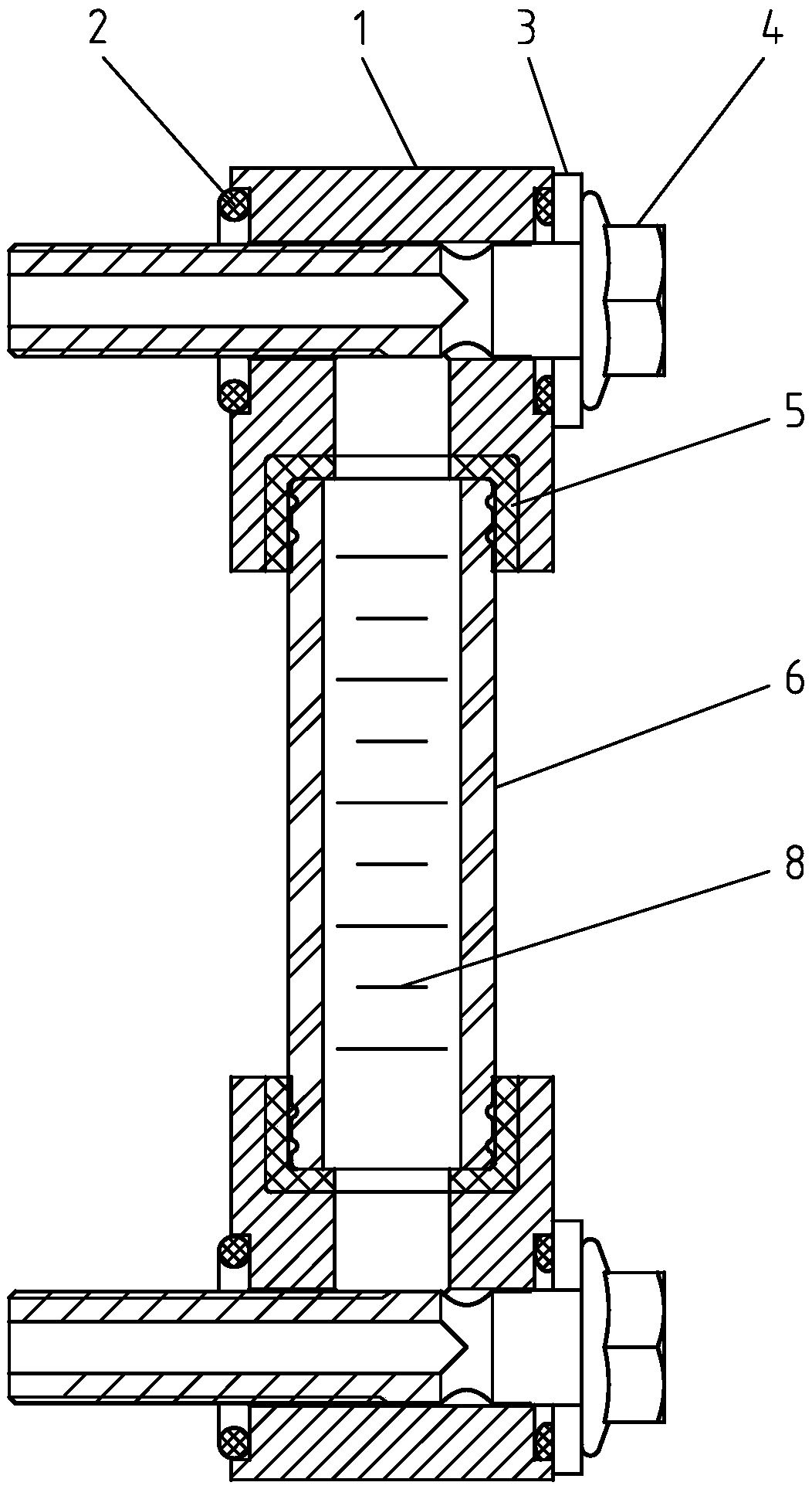
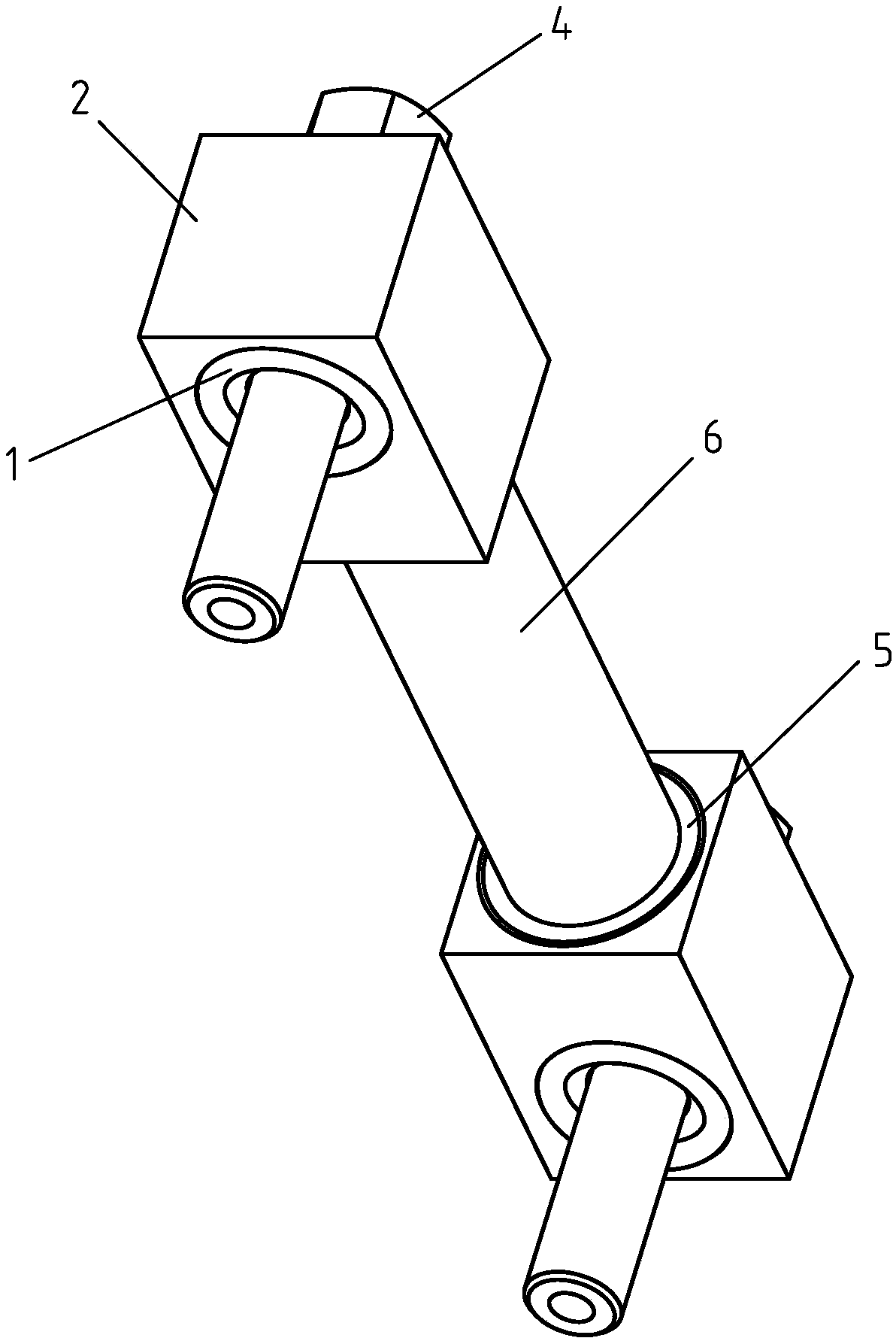
[0034] Reference figure 1 As shown in the figure, an invented high-temperature-resistant visualized liquid position display device includes upper and lower mounting blocks 1 and a tempered glass tube 6, and both ends of the tempered glass tube 6 are sealed and connected to the upper and lower mounting blocks 1 respectively The upper and lower mounting blocks 1 are connected to the liquid storage device by bolts 4. Both ends of the mounting block 1 are provided with "O"-shaped sealing rings. The tempered glass tube 6 is also provided with scale marks 8.

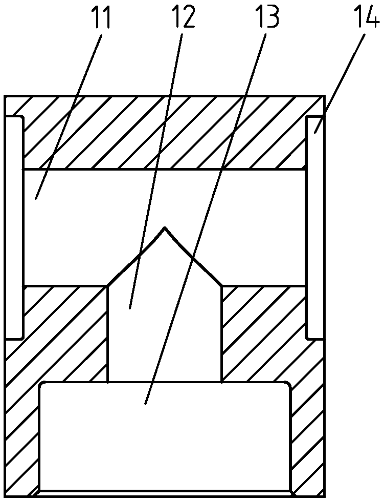
[0035] Combine Figure 3-Figure 6 , The upper and lower mounting blocks 1 are symmetrical in structure. Each mounting block 1 is provided with a "T"-shaped hole, and the "T"-shaped hole includes a longitudinal blind hole 12 communicating with the tempered glass tube 6 and a transverse through hole 11 for the bolt to pass through; The two ends of the through hole 11 are also provided with sealing ring installation grooves 14 fo...


PUM


Abstract

The invention discloses a heat-resistant visual liquid position display device. The device comprises an upper mounting block, a lower mounting block and a tempered glass tube, and is characterized inthat the two ends of the tempered glass tube are in sealed connection with the upper mounting block and the lower mounting block respectively; the upper mounting block and the lower mounting block areconnected to liquid storage equipment through bolts; each mounting block is internally provided with a 'T'-shaped hole, each 'T'-shaped hole comprises a longitudinal blind hole communicated with thetempered glass tube and a transverse through hole allowing the corresponding bolt to pass trough the corresponding transverse through hole, and the two ends of each transverse through hole are provided with 'O'-shaped sealing rings; and each bolt is further provided with a liquid flow passage communicated with the corresponding longitudinal blind hole and liquid in the liquid storage equipment. The liquid position display device adopts the tempered glass tube as an observation body. Since the tempered glass tube has high strength, high security and good heat stability, the heat-resistant visual liquid position display device can be applied to various occasions of which the liquid is low-temperature, high-temperature or high-temperature and high-pressure.

Description

Technical field [0001] The invention relates to the technical field of engineering machinery and fluid machinery, in particular to a visualization device for displaying the liquid position and liquid volume of a heat exchanger of engineering machinery, in particular to a high-temperature resistant visualization liquid position display device. Background technique [0002] In the field of industrial applications, many occasions need to use the liquid position display structure to display the level of the liquid position in certain equipment, pipelines, and containers. Such as mining trucks, large loaders, large hydraulic excavators and chemical equipment cooling systems. [0003] The main body of the conventional liquid level display device is composed of a rectangular transparent piece, and a liquid guiding channel is provided on the transparent piece. The liquid level display device of this structure has a rectangular parallelepiped structure to facilitate the connection with the...

Claims


Application Information

Patent Timeline
IPC IPC(8): G01F23/02
CPCG01F23/02
Inventor 孙小桥
Owner ZHEJIANG YINLUN MACHINERY
Learn More