Power distribution cabinet with strong heat dissipation and moisture resistance

A power distribution cabinet, moisture-proof technology, applied in the substation/power distribution device shell, electrical components, substation/switch layout details, etc., can solve the problem that the power distribution cabinet cannot be transferred when it is thrown in place, the life of electronic components is shortened, and the total resistance High value and other problems, to achieve enhanced waterproof effect, good moisture-proof and cooling effect, and improved moisture-proof effect

Inactive Publication Date: 2018-10-12
盐城同舟电气有限公司
View PDF0 Cites 0 Cited by
  • Summary
  • Abstract
  • Description
  • Claims
  • Application Information

AI Technical Summary

Problems solved by technology

Since a large number of electronic and electrical components and a large number of wires are installed in the power distribution cabinet, the total resistance value in the power distribution cabinet is very high, and a large amount of heat will be emitted during work. When the power distribution cabinet is working outdoors , will cause the temperature inside the power distribution cabinet to rise, resulting in shortened life or failure of electronic components
When the existing power distribution cabinets work outdoors, it is easy to cause water ingress on rainy days, and the power distribution cabinets in the prior art are often fixed installations. Once natural disasters, such as floods, etc., the power distribution cabinets can only be thrown away. cannot be transferred

Method used


Image

  • Power distribution cabinet with strong heat dissipation and moisture resistance
  • Power distribution cabinet with strong heat dissipation and moisture resistance

Examples


Embodiment Construction

[0017] The following will clearly and completely describe the technical solutions in the embodiments of the present invention with reference to the accompanying drawings in the embodiments of the present invention. Obviously, the described embodiments are only some, not all, embodiments of the present invention.

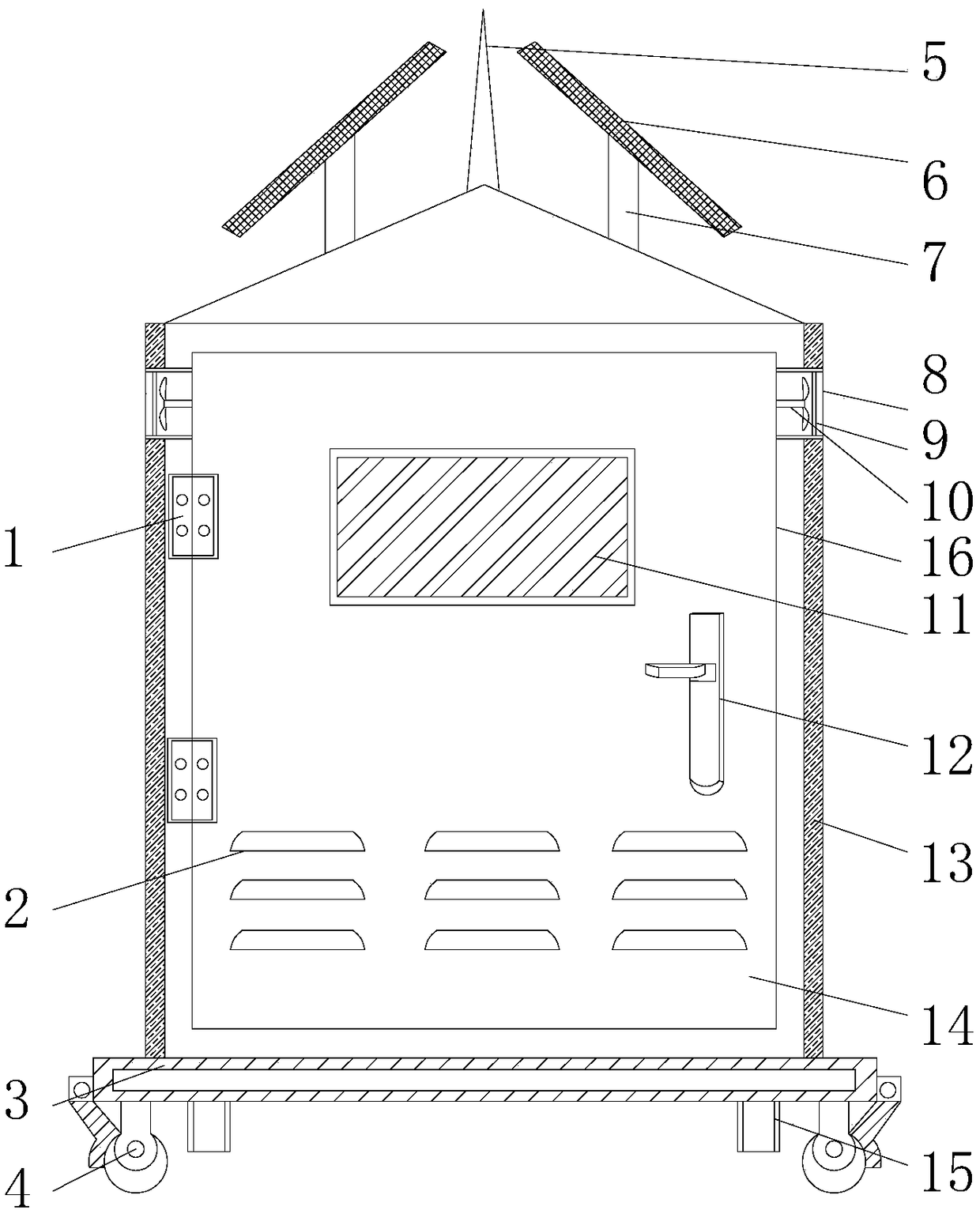
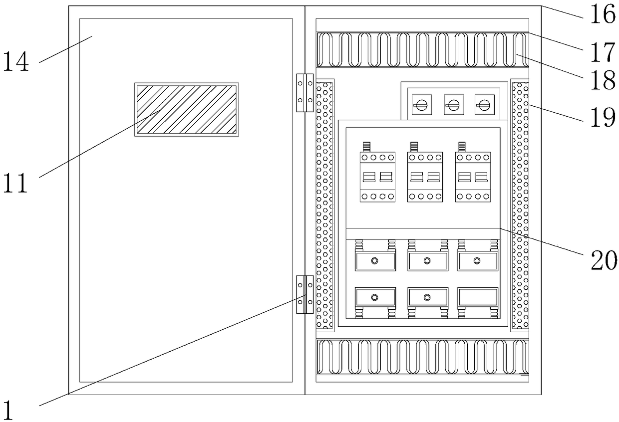
[0018] refer to Figure 1-2 , a power distribution cabinet with strong heat dissipation and moisture resistance, including a door body 14, a casing 16 and an electrical box 20, the casing 16 is detachably connected to the door body 14 through a hinge 1, and the surface of the door body 14 is provided with an observation window 11 , a handle 12 is fixed below the observation window 11, a number of cooling holes 2 are provided under the handle 12, ventilation holes 8 are provided on both sides of the housing 16, and an exhaust fan 10 is arranged inside the ventilation hole 8, and the exhaust fan 10 The outer side is provided with a filter screen 9, the inside of the ho...


PUM


Abstract

The invention discloses a power distribution cabinet with strong heat dissipation and moisture resistance, comprising a door body, a shell and an electric box, wherein the shell is detachably connected with the door body through a hinge; the surface of the door body is provided with an observation window; the bottom of the observation window is fixed with a handle; a plurality of heat dissipationholes are formed under the handle; ventilation holes are formed on both sides of the shell; an exhaust fan is arranged inside the ventilation holes; a filter net is arranged outside the exhaust fan; an electric box is arranged inside the shell; condensation tanks are arranged on the upper and lower sides of the electric box; the condensation tanks on both sides are symmetrically distributed alongthe horizontal center line of the shell; a condensing coil is arranged inside the condensation tank; and bamboo charcoal boxes are fixed on both sides of the electric box. The power distribution cabinet with strong heat dissipation and moisture resistance in the invention absorbs moisture into the bamboo charcoal through the bamboo charcoal boxes, thereby improving the overall moisture resistance;and the condensation tanks are arranged on the upper and lower sides of the electrical box, thereby reducing the heat generated by continuous operation of the power distribution cabinet and prolonging the service life.

Description

technical field [0001] The invention relates to the technical field of electrical box equipment, in particular to a power distribution cabinet with strong heat dissipation and moisture resistance. Background technique [0002] Power distribution cabinets are divided into power distribution cabinets, lighting distribution cabinets, and metering cabinets. They are the final equipment of the power distribution system. Power distribution cabinets are collectively referred to as motor control centers. ;The power distribution cabinet is the final equipment of the power distribution system. Power distribution cabinets are widely used in the production and distribution of industries and enterprises. Due to their wide range of applications, power distribution cabinets often need to be used in more complex environments, such as outdoors or fields where the temperature and humidity cannot be controlled. Since a large number of electronic and electrical components and a large number of...

Claims


Application Information

Patent Timeline
IPC IPC(8): H02B1/56H02B1/30H02B1/28
CPCH02B1/565H02B1/28H02B1/30
Inventor 张华
Owner 盐城同舟电气有限公司
Why Eureka
Try Eureka