
Multifunctional automatic phase changing system for medium/low voltage line and phase changing method thereof

A low-voltage line, multi-functional technology, which is applied to the multi-functional automatic commutation system of medium and low voltage lines and its commutation field, can solve problems such as three-phase load imbalance, achieve energy-saving electricity prices, improve the utilization rate of electric energy, and reduce line losses Effect

Active Publication Date: 2018-10-12
ANHUI ZENITH ELECTRICITY & ELECTRONICS
View PDF7 Cites 6 Cited by
  • Summary
  • Abstract
  • Description
  • Claims
  • Application Information

AI Technical Summary

Problems solved by technology

[0005] Aiming at the deficiencies of the prior art, the present invention provides a multifunctional automatic phase change system and its phase change method for medium and low voltage lines, which has the advantages of energy saving and high real-time performance, and solves the problem of unbalanced three-phase load in the distribution station area

Method used


Image

  • Multifunctional automatic phase changing system for medium/low voltage line and phase changing method thereof
  • Multifunctional automatic phase changing system for medium/low voltage line and phase changing method thereof
  • Multifunctional automatic phase changing system for medium/low voltage line and phase changing method thereof

Examples


Embodiment 1

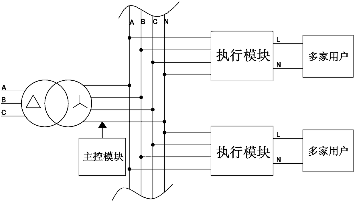
[0057] see figure 1 , the multifunctional automatic phase change system for medium and low voltage lines in this embodiment is applied in a power distribution station area, and the phase change system includes a main control module arranged at the transformer end of the station area, and a plurality of execution modules arranged at the user end, wherein each The execution module corresponds to multiple users connected in parallel.

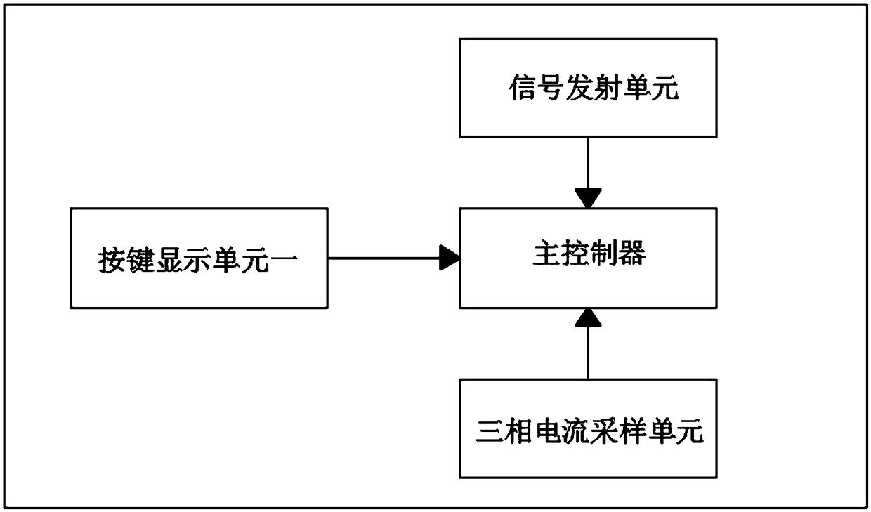
[0058] see figure 2 , the main control module includes a main controller, a three-phase current sampling unit, a key display unit 1, and a signal transmitting unit. The three-phase current sampling unit is used to detect the three-phase current I output by the transformer in real time A , I B , I C . The signal transmitting unit is used to remotely transmit the current information detected by the three-phase current sampling unit to the main station of the power grid, and can also transmit other information to the main station. The signal tr...

Embodiment 2

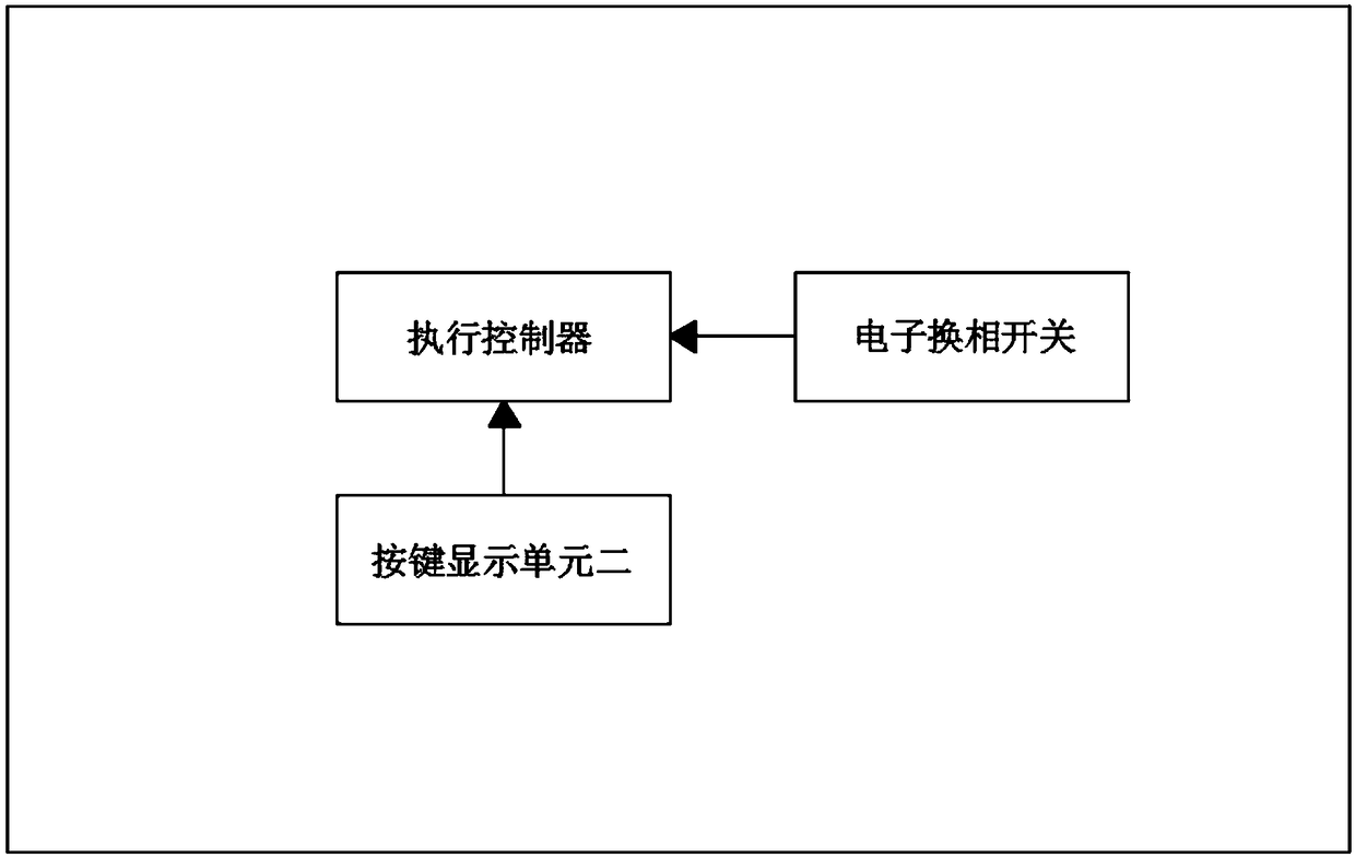
[0070] see Figure 5 as well as Figure 6 On the basis of Embodiment 1, the multifunctional automatic phase commutation system for medium and low voltage lines in this embodiment adds a voltage sampling unit and an aging alarm device installed in the execution module. The voltage sampling unit detects the voltage at both ends of the electronic commutation switch when the electronic commutation switch is closed, and the executive controller judges whether the voltage difference between the two ends of the electronic commutation switch exceeds a preset voltage difference, and if so, the executive controller drives the aging alarm device to alarm.

[0071] In other embodiments, after the electronic commutation switch is closed, its voltage fluctuates within a preset time two, and reaches a steady state after a preset time two. The voltage sampling unit can also detect the peak voltage within the preset time two after the electronic commutation switch is closed, and the steady vo...

Embodiment 3

[0074] see Figure 7 as well as Figure 8 , The multifunctional automatic phase commutation system for medium and low voltage lines in this embodiment adds a current sampling unit and an aging alarm device installed in the execution module on the basis of Embodiment 1. After the electronic commutation switch is closed, its current fluctuates within a preset time two, and reaches a steady state after the preset time two; the current sampling unit detects the peak current within the preset time two after the electronic commutation switch is closed, and The steady current is reached after the preset time two; the execution controller judges whether the voltage difference between the peak current and the steady current exceeds a preset current difference, and if so, the execution controller drives the aging alarm device to alarm.

[0075] The multifunctional automatic phase change system for medium and low voltage lines in this embodiment is suitable for aging alarm monitoring wh...


PUM


Abstract

The invention discloses a multifunctional automatic phase changing system for a medium / low voltage line and a phase changing method thereof. The phase changing system comprises a master control moduleand multiple execution modules; each execution module corresponds to multiple users that are connected in parallel; the master control module comprises a master controller and a three-phase current sampling unit; each execution unit includes an electronic phase changing switch; and the electronic phase changing switch selects, according to a switching command, one phase corresponding to the switching command from three power supply phases of a transformer to supply a power to the multiple users corresponding to the execution modules. According to the multifunctional automatic phase changing system for the medium / low voltage line and the phase changing method thereof, the master control module and the execution modules are provided, lines in a power distribution area are divided, and the multiple execution modules are controlled via the master control module arranged at a power distribution transformer end to switch three phases of each line, so that three-phase power loads of all switched lines tend to balance; and thus, the unbalancedness of the three phases is improved, the line loss of the power distribution area is reduced, the power quality of the users is guaranteed, and thepurposes of saving the energy and reducing an electricity price are implemented.

Description

technical field [0001] The invention relates to an automatic phase change system and a phase change method thereof in the technical field of smart grids, in particular to a multifunctional automatic phase change system and a phase change method for medium and low voltage lines. Background technique [0002] Three-phase load balance is the basis of safe power supply, and unbalanced three-phase load will reduce the power supply efficiency of lines and distribution transformers if it is light, or it will cause a certain phase wire to burn out and a switch to burn out due to heavy load phase overload , and even serious consequences such as single-phase burnout of distribution transformers. Therefore, only the three-phase impedance balance can ensure the good operation of the low-voltage leakage protection and prevent personal electric shock casualties, and only the three-phase load balance can ensure the user's power quality. The balance of the three-phase load is also the basi...

Claims


Application Information

Patent Timeline
Patent Type & Authority Applications(China)
IPC IPC(8): H02J3/26
CPCG01R31/086H02J3/26Y02E40/50
Inventor 明小慧杨黄河王太平张小龙赵伟
Owner ANHUI ZENITH ELECTRICITY & ELECTRONICS
Learn More