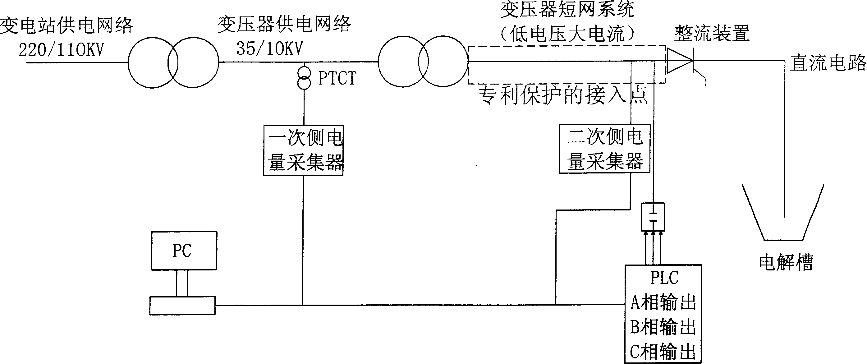
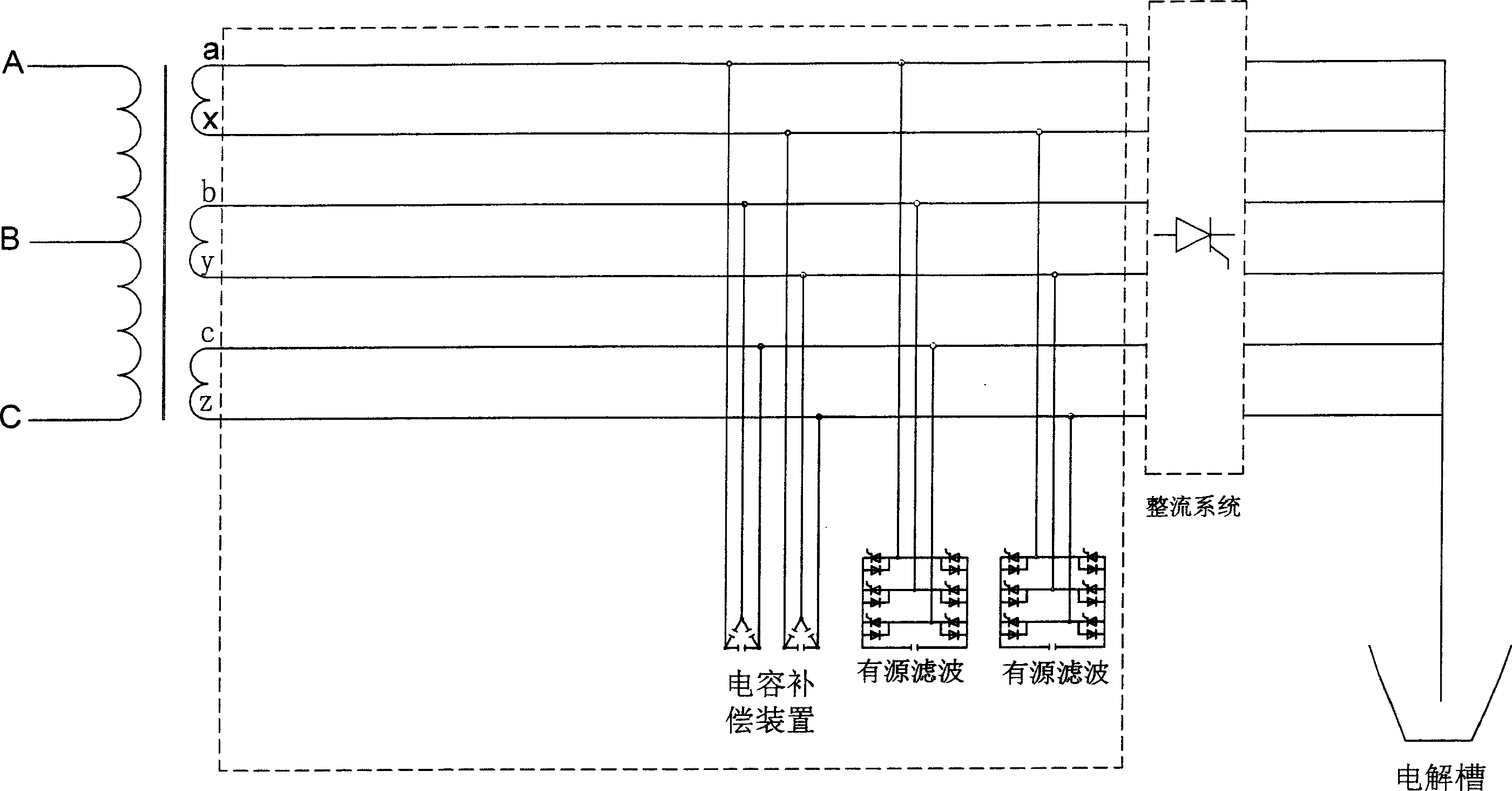
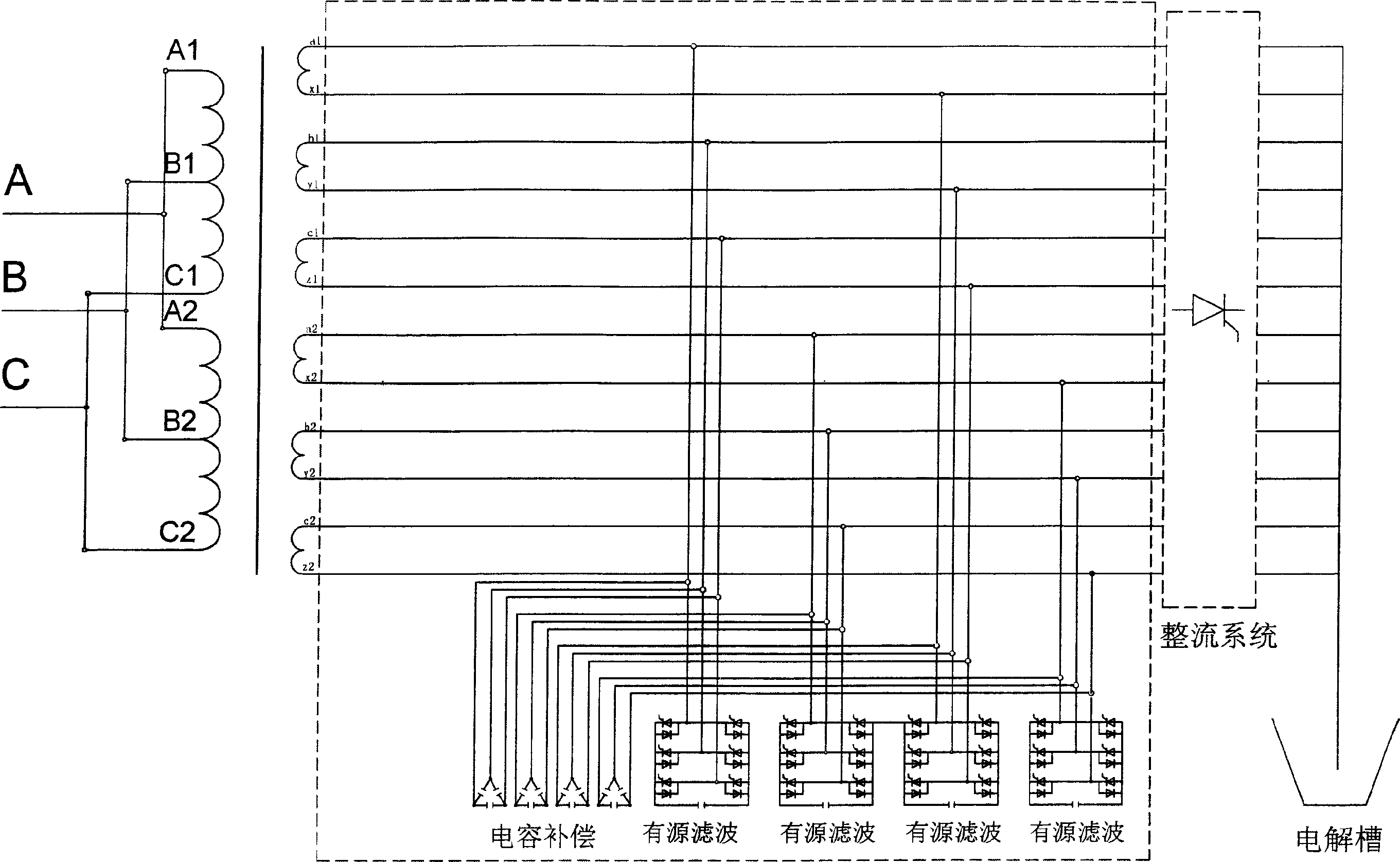
Method for low-voltage connecting reactive-load compensation device and active filtering device by electrolysis system transformer

A filter device, electrolysis system technology, applied in reactive power compensation, reactive power adjustment/elimination/compensation, harmonic reduction devices, etc., can solve problems such as increased harmonic harm, inaccurate measurement of electrical measuring instruments, and overheating of lines , to improve the ability to transmit active power, achieve asymmetric control, and reduce line loss.

Inactive Publication Date: 2006-12-20
西安汇丰电力设备有限公司
View PDF0 Cites 12 Cited by
  • Summary
  • Abstract
  • Description
  • Claims
  • Application Information

AI Technical Summary

Problems solved by technology

[0006] 2. Harmonics cause additional harmonic loss to the components in the public grid, reducing the efficiency of power generation, transmission and power consumption equipment. When a large number of third harmonics flow through the neutral line, the line will overheat and even cause a fire
[0007] 3. Affect the normal work of various electrical equipment
The influence of harmonics on the motor will not only cause additional loss, but also produce mechanical vibration, noise and overvoltage, which will cause local serious overheating of the electrolysis device
Harmonics cause overheating of capacitors, cables and other equipment, aging of insulation, shortening of life, and damage
[0008] 4. Harmonics will cause local parallel resonance and series resonance in the public power grid, thereby amplifying the harmonics, greatly increasing the harm of harmonics, and even causing serious accidents
[0009] 5. Ha

Method used


Image

  • Method for low-voltage connecting reactive-load compensation device and active filtering device by electrolysis system transformer
  • Method for low-voltage connecting reactive-load compensation device and active filtering device by electrolysis system transformer
  • Method for low-voltage connecting reactive-load compensation device and active filtering device by electrolysis system transformer

Examples


Example Embodiment

[0055] Examples:

[0056] Picture 9 It is the test effect diagram of the low-voltage side active filter device of the electrolysis device with a capacity of 150KVar and an operating voltage of 10kV running on the low-voltage side of a power distribution electrolysis device with a model of S7-35 / 10 and a capacity of 5000KVA.

[0057] The low-voltage side active filter device of the electrolysis device, which combines the active filter device of the transmission network and the secondary reactive power compensation device of the electrolysis device, can compensate reactive power and control harmonics from the source, achieving dynamic real-time compensation and On-site compensation can achieve the purpose of energy saving and consumption reduction and increase output, which has good social and economic benefits.

[0058] To sum up, the active filter device of the electrolysis system has the following outstanding substantive features compared with the previous active filter device, ...


PUM


Abstract

The invention relates to a transformer low-voltage connection passive compensation of electrolysis system and relative active filter device, wherein the secondary side of transformer is connected to the rectifying device and the electrolytic tank; the secondary side of transformer is parallel connected to the rectifying device and connected to at least one group of capacitor compensators and one group of active filters; one end of first group of capacitors is connected to the main circuit of secondary side of transformer; one end of second capacitors is connected to the main circuit of end of secondary side of transformer; another end of two groups of capacitors are parallel or serially connected; one end of first group of active filters is connected to the main circuit of secondary side of transformer; one end of second group is connected to the main circuit of the end of secondary side; another end of two groups of active filters is connected to the capacitor or the inductor. The invention passively treats the harmonic wave from source, with dynamic and on-site compensation, to save energy and increase yield.

Description

technical field [0001] The invention relates to reactive power compensation and harmonic elimination of electric power grid, and is especially suitable for the method of reactive power compensation and active filtering device for low-voltage connection of electrolytic system transformers. Background technique [0002] In order to ensure the power quality of the power supply, the power system generally installs reactive power compensation and harmonic elimination devices on the high-voltage side of the electrolysis device, that is, the transmission system. The root cause of reactive power and harmonics is to exchange energy with the reactive power compensation device installed on the high-voltage side through the low-voltage side of the electrolysis device and the line on the low-voltage side. The exchange path is long, and dynamic real-time compensation and on-site compensation cannot be achieved. Therefore, Using modern control technology to install the capacitor reactive p...

Claims


Application Information

Patent Timeline
IPC IPC(8): H02J3/18H02J3/01
CPCY02E40/30Y02E40/40
Inventor 王昀睿
Owner 西安汇丰电力设备有限公司
Why Eureka
Try Eureka