Piezoelectric energy storage device for oil well downhole detection equipment

A technology for downhole detection and piezoelectric energy storage, applied in piezoelectric effect/electrostrictive or magnetostrictive motors, electrical components, generators/motors, etc. Problems such as power supply problems, promotion and application problems, etc., to achieve the effect of simple structure, low cost and wide application

Active Publication Date: 2018-10-12
NORTHEAST GASOLINEEUM UNIV
View PDF5 Cites 4 Cited by
  • Summary
  • Abstract
  • Description
  • Claims
  • Application Information

AI Technical Summary

Problems solved by technology

[0002] Mechanical oil recovery is the main oil recovery method in domestic and foreign oil fields. The efficient operation of downhole equipment is the key to the efficiency of the mechanical recovery system. Therefore, effective monitoring of the operating status of downhole equipment and real-time adjustment of oil production parameters are the core of oilfield management. The promotion and application of monitoring equipment has always been a problem. For example, downhole dynamometers used to monitor the operating status of oil well pumps, intelligent water distributors used to monitor and adjust the injection volume of water injection layers, etc. These devices require continuous power supply. Due to the limitation of wellbore space, continuous power supply downhole has become a problem, resulting in the application of downhole monitoring equipment is still in the experimental research stage

Method used


Image

  • Piezoelectric energy storage device for oil well downhole detection equipment
  • Piezoelectric energy storage device for oil well downhole detection equipment
  • Piezoelectric energy storage device for oil well downhole detection equipment

Examples


Embodiment Construction

[0026] In order to make the technical means, creative features, goals and effects achieved by the present invention easy to understand, the present invention will be further described below in conjunction with specific embodiments.

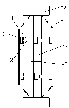
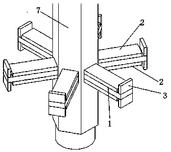
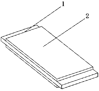
[0027] refer to Figure 1-Figure 5, the specific embodiment adopts the following technical solutions: a piezoelectric energy storage device for oil well downhole detection equipment, including a cantilever beam base 1, a piezoelectric ceramic sheet 2, a mass 3, a protective cover 4, a threaded thread 5 and The upper and lower ends of the circuit board 6 and the cylindrical main body 7 are provided with screw threads 5, and the threaded screws 5 are connected with the sucker rod column. The cantilever beam base 1 is arranged in multiple rows on the circumference of the cylindrical main body 7. The cantilever beam base 1. Piezoelectric ceramic sheets 2 are pasted on the upper and lower sides by conductive glue. The mass block 3 is provided at the en...


PUM


Abstract

The invention discloses a piezoelectric energy storage device for oil well downhole detection equipment. The upper and lower ends of a cylindrical body are provided with threaded screw threads; the threaded screw threads are connected with a sucker rod string; multiple rows of cantilever beam substrates are arranged on the circumference of the cylindrical body in parallel; piezoelectric ceramic pieces are adhered to the upper and lower sides of the cantilever beam substrates through a conductive adhesive; a mass block is arranged at the tail end of each cantilever beam substrate; the mass block is not in contact with the sucker rod string; a protective cover is also arranged outside the cylindrical body; a circuit board is arranged at the middle part of the cylindrical body; and an unstable current generated by the piezoelectric ceramic pieces passes through a booster circuit, a rectifying circuit and a load matching circuit to obtain a stable direct current for storage so as to be used by a load. The piezoelectric energy storage device for the oil well downhole detection equipment provided by the invention is simple in structure; and energy generated by the vibration shock of a downhole fluid in the oil pumping process can be converted into available electric energy, and the electric energy is stored in a rechargeable battery to be used by the downhole detection equipment.

Description

technical field [0001] The present invention relates to the combination of the field of mechanical oil recovery engineering research and the field of electrical technology, and in particular relates to energy obtained from downhole liquid vibrations in oil wells, transformed and stored in piezoelectric energy storage devices, and is suitable for energy obtained from vibration environments for conversion and application In particular, it relates to a piezoelectric energy storage device used for downhole detection equipment in oil wells. Background technique [0002] Mechanical oil recovery is the main oil recovery method in domestic and foreign oil fields. The efficient operation of downhole equipment is the key to the efficiency of the mechanical recovery system. Therefore, effective monitoring of the operating status of downhole equipment and real-time adjustment of oil production parameters are the core of oilfield management. The promotion and application of monitoring eq...

Claims


Application Information

Patent Timeline
IPC IPC(8): H02N2/18
CPCH02N2/185
Inventor 王素玲姜民政宋微董康兴宋健李金波冯子明王雪飞
Owner NORTHEAST GASOLINEEUM UNIV
Why Eureka
Try Eureka