Eureka AIR delivers breakthrough ideas for toughest innovation challenges, trusted by R&D personnel around the world.

Magnetic direct drive type stirrer

A direct-drive, mixer technology, applied in the field of mixers, can solve problems such as bulky, inconvenient disassembly and assembly, complex structure, etc., and achieve the effects of simplifying the base mechanism, facilitating cleaning, and reducing transmission devices

Inactive Publication Date: 2018-10-16
WUHAN UNIV OF TECH
View PDF6 Cites 1 Cited by
  • Summary
  • Abstract
  • Description
  • Claims
  • Application Information

AI Technical Summary

Problems solved by technology

However, this invention is still driven by a traditional motor, and the active magnet is driven to rotate through a transmission mechanism such as a gear and a shaft, which has the disadvantages of complex structure, large volume, large energy consumption, and inconvenient assembly and disassembly.

Method used


Image

  • Magnetic direct drive type stirrer
  • Magnetic direct drive type stirrer
  • Magnetic direct drive type stirrer

Examples


Embodiment 1

[0052] Embodiment 1 provided by the present invention is: a flat magnetic direct-drive mixer

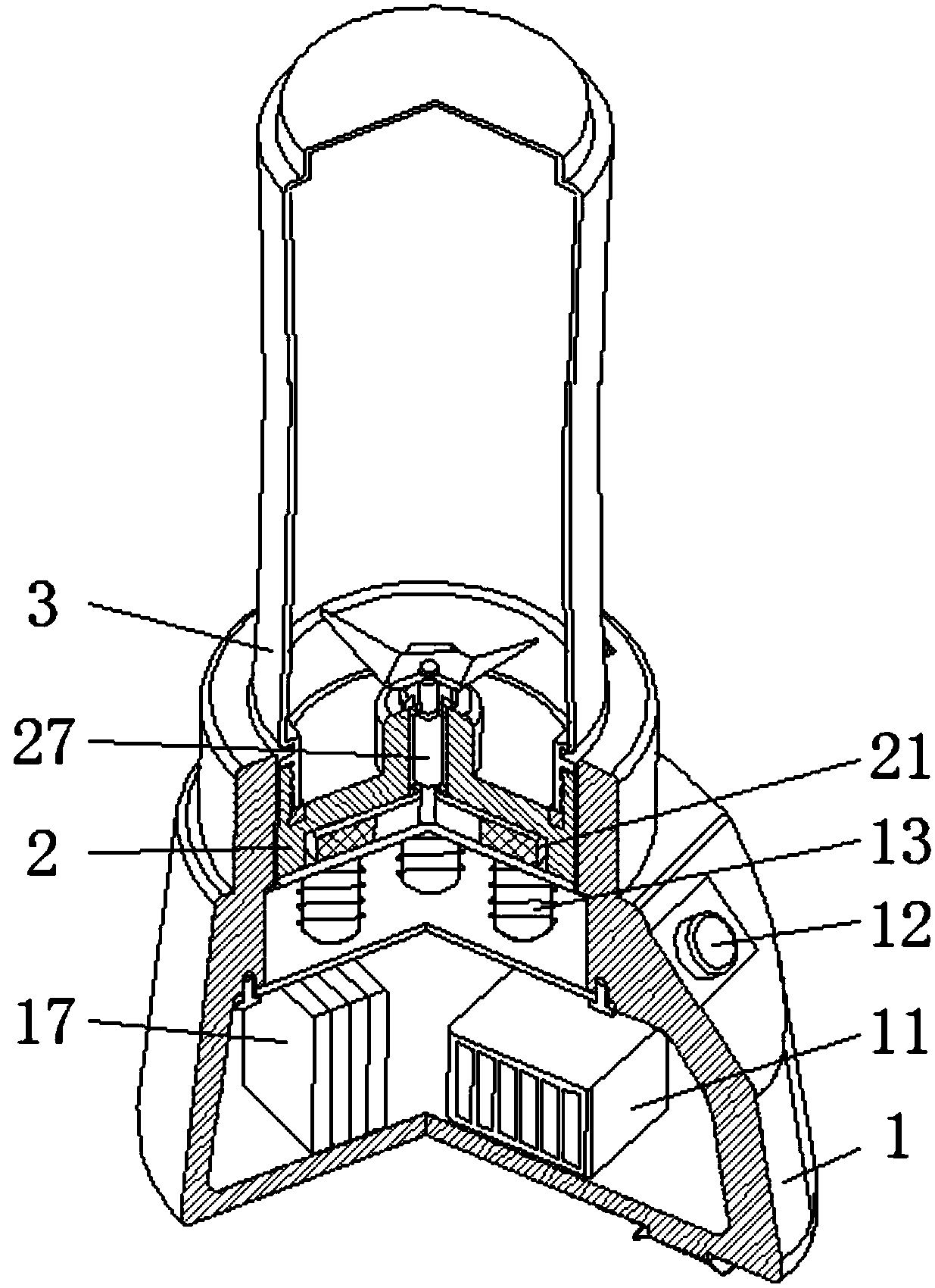
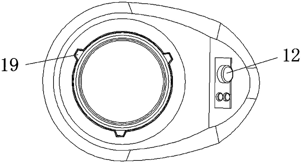
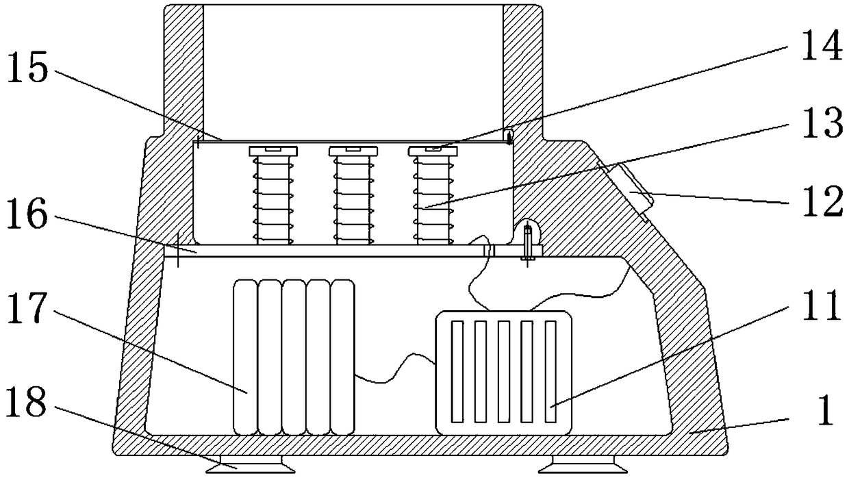
[0053] Refer below Figure 1 to Figure 6 The application is further described, including a base 1, a cup cover 2 and a stirring cup 3, wherein the magnetodynamic active element-electromagnet group 13, the position sensor-Hall element 14 are arranged in the upper compartment of the base 1, the driver 11 and the The charging power supply 17 is arranged in the lower compartment of the base 1 . The bottom plate 16 is used to separate the upper and lower compartments of the base 1, the driven permanent magnet group 21 is arranged in the cup cover 2, and the base 1 and the cup cover 2 are connected in a plane.

[0054] The rechargeable power supply 17, the driver 11, and the electromagnet group 13 are connected in sequence, and then the driver 11 is connected to the control panel 12 in addition.

[0055] Three adjacent position sensors—Hall elements 14 are placed on the top of the electr...

Embodiment 2

[0064] Embodiment 2 provided by the present invention is a coaxial magnetic direct drive mixer

[0065] Refer below Figure 7 ~ Figure 10 The application is further described, including a base 1, a cup cover 2 and a stirring cup 3, wherein the magnetodynamic active element-electromagnet group 13, the position sensor-Hall element 14 are arranged in the upper compartment of the base 1, the driver 11 and the The charging power supply 17 is arranged in the lower compartment of the base 1 . The bottom plate 16 is used to separate the upper and lower compartments of the base 1 . The driven permanent magnet group 21 is arranged in the cup cover 2, and the base 1 and the cup cover 2 are connected by a concave-convex platform.

[0066] The electromagnet groups 13 are evenly arranged in a horizontal circle, and 12 are initially preferred, and a three-phase symmetrical star connection is adopted. The iron core of the electromagnet group 13 is made of stacked silicon steel sheets, whic...


PUM

PropertyMeasurementUnit
Thicknessaaaaaaaaaa

Abstract

The invention discloses a magnetic direct drive type stirrer. The magnetic direct drive type stirrer comprises a base, a cup cover and a stirring cup which are sequentially arranged, wherein an electromagnet group, a position sensor, a drive device and a rechargeable power supply are arranged in the base, the position sensor is arranged on the electromagnet group, the drive device is connected with the rechargeable power supply, the position sensor and the electromagnet group, a driven permanent magnet group is arranged in the cup cover, the driven permanent magnet group is connected with a blade, a contact face between the base and the cup cover is a plane, the electromagnet group drives the driven permanent magnet group to rotate through magnetic force, further, the blade is driven to rotate, and the stirring processing for food is realized; the electromagnet group serves as the magnetomotive driving element. The driving of a motor is not needed, the electromagnetic drive is directlyadopted, the transmission devices including a gear and a coupler for transmitting energy are not needed, therefore, the structure is greatly simplified, the energy consumption is reduced, in addition, the transmission is stable, the speed can be freely controlled, and the magnetic direct drive type stirrer is suitable for stirring various foods.

Description

technical field [0001] The invention relates to the technical field of mixers, in particular to a magnetic direct-drive mixer. Background technique [0002] A traditional juicer or blender mainly includes a mixing cup and a cup holder, both of which are driven by a motor. Through transmission devices such as gear meshing and couplings, the force and torque are transmitted to the rotating shaft, which drives the upper blade to rotate at high speed to cut fruit. Or vegetables, such a device has a complex structure, many transmission stages, large energy loss, and large noise. [0003] The contact surface between the lid and the base of the traditional juice extractor is used to transmit power, which is uneven, difficult to clean, and heats up severely during operation, so it cannot be used for a long time. [0004] Moreover, most of the existing juice extractors or blenders have a fixed speed, and one product cannot process fruits, vegetables or meat at the same time, and the...

Claims


Application Information

Patent Timeline
IPC IPC(8): A47J19/00A47J43/046A47J43/08A47J43/07
CPCA47J19/00A47J43/0465A47J43/0716A47J43/085
Inventor 吴华春徐鑫鑫张丽胡业发程鑫王隆扬
Owner WUHAN UNIV OF TECH
Why Eureka
Eureka Blog
Learn More