[0008]One development of the invention provides that the
planet gear carrier is rotatably mounted and connected to the driven shaft in a rotationally fixed fashion, and in particular is embodied in one piece therewith. The output of the reducing gear, for example on the internal combustion engine side, therefore occurs via the
planet gear carrier. For this purpose, the latter is rotatably mounted and has a rotationally fixed connection to the driven shaft. It may be particularly advantageous to embody the
planet gear carrier in one piece with the driven shaft in order to achieve a reduction in weight of the reducing gear. For example, the reducing gear can have a rotationally fixed connection between the sun gear and the
drive shaft as well as between the planet gear carrier and the driven shaft, while the ring gear is arranged in a fixed fashion.
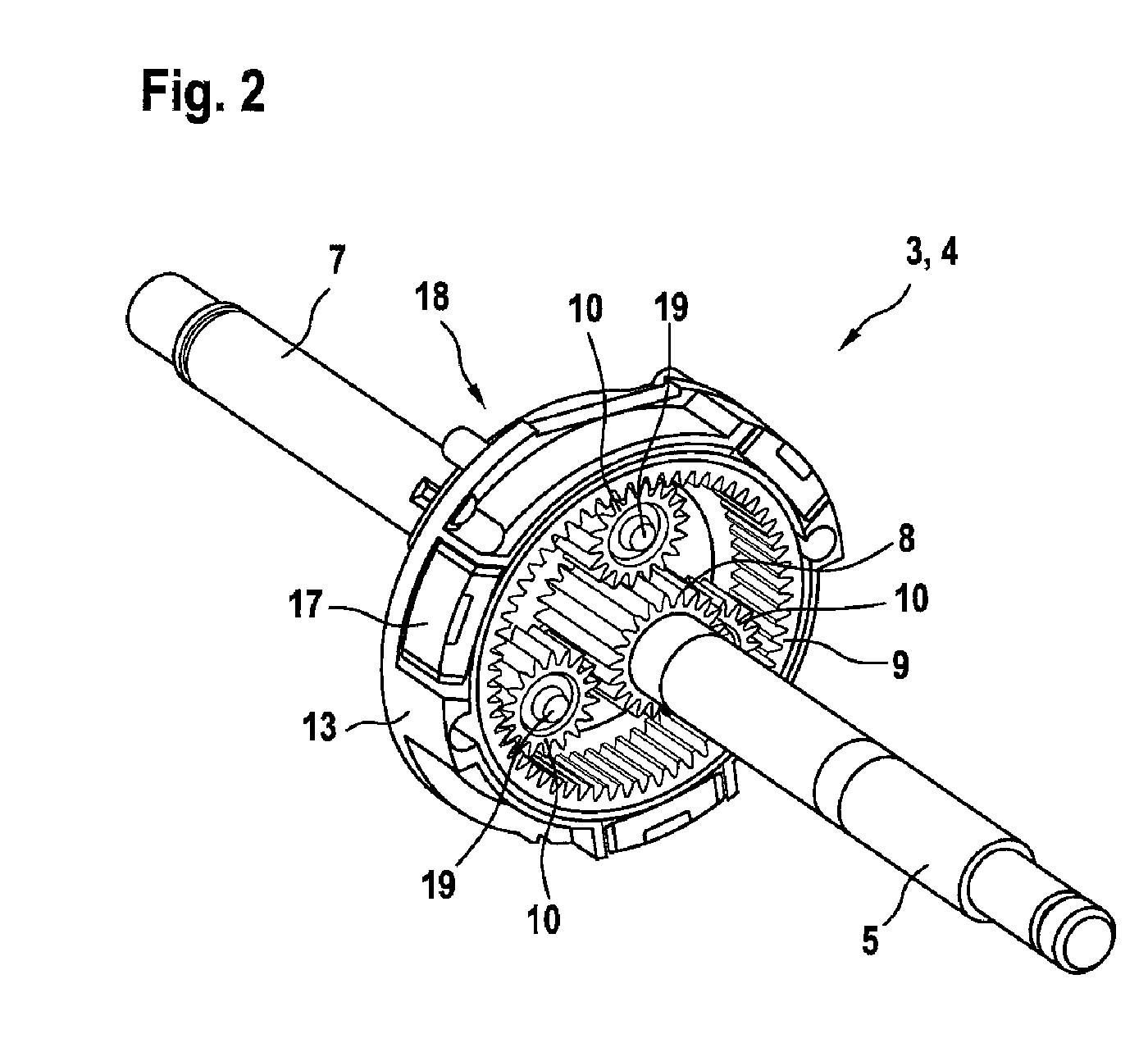
[0007]One development of the invention provides that the at least one planet gear is rotatably arranged on a planet gear carrier. The planet gear carrier serves to
mount the at least one planet gear in a rotatable fashion. The planet gear carrier can be mounted in a fixed or rotatable fashion. In the case of a planetary gear mechanism, either the ring gear or the planet gear carrier always has to be rotatably arranged. The planet gear carrier therefore holds the at least one planet gear between the sun gear and the ring gear so that the toothing of the planet gear can engage both with the sun gear and with the ring gear.
[0008]One development of the invention provides that the planet gear carrier is rotatably mounted and connected to the driven shaft in a rotationally fixed fashion, and in particular is embodied in one piece therewith. The output of the reducing gear, for example on the internal combustion engine side, therefore occurs via the planet gear carrier. For this purpose, the latter is rotatably mounted and has a rotationally fixed connection to the driven shaft. It may be particularly advantageous to embody the planet gear carrier in one piece with the driven shaft in order to achieve a reduction in weight of the reducing gear. For example, the reducing gear can have a rotationally fixed connection between the sun gear and the drive shaft as well as between the planet gear carrier and the driven shaft, while the ring gear is arranged in a fixed fashion.
[0009]One development of the invention provides that the extra deep toothing has an effective minimum profile coverage of approximately two or more than two between the sun gear and the planet gear and / or between the ring gear and the planet gear. A significant objective of the configuration of the extra deep toothing is to configure the tooth height in such a way that the uncorrected evolvent range brings about an effective minimum profile coverage of ≧2 between the sun gear and the at least one planet gear and between the at least one planet gear and the ring gear, respectively. This condition is met if the
diameter of the reference circle DFa is selected such that the engagement distance ga obeys the relation ga=2*pe, where pe is the (end face) engagement
pitch; the profile coverage εα is the ratio of the engagement distance to the end face engagement
pitch pe. The end face engagement
pitch pe=m*π / cos(α) is the distance between two right-hand or left-hand edges on the engagement line. This can also be aimed at, for example, within the course of optimization of load-bearing capabilities. As a result, the requirements made in terms of optimum
noise behavior and vibration behavior, on the one hand, and sufficient strength of the gearwheels, on the other, are met. The increase in the profile coverage occurs, inter alia, through the use of a reduced modulus for a specific
transmission ratio at the gearwheel pair, which is confirmed by the following consideration: the modulus used has to be selected suitable for the strength so that sufficiently load-bearing tooth bases can be formed. The minimum
usable modulus has been found experientially to be 0.5 mm. However, this value is only to be understood as a starting point since a lower modulus may be possible by using improved materials.
[0010]One development of the invention provides that the extra deep toothing has a normal engagement angle of 10° to 20°, preferably approximately 10° or approximately 16°. The reduction in the normal engagement angle for the extra deep toothing results in steeper edges, a larger profile coverage and smaller radial forces. Compared to a conventional geometry, the extra deep toothing is therefore less sensitive to wheel base deviations and out-of-true running errors, and the running is also made smoother. In toothings which are fabricated in a non-
metal-removing fashion, the engagement angle can be reduced to approximately 10°, in particular if the profile coverage is ≧2. If the toothing is roller-milled, the engagement angle can be reduced, for example, as far as 16°. Through suitable measures, for example by increasing the strength by selecting a different material, the normal engagement angle can also assume smaller values than 10°.
[0011]One development of the invention provides that tooth bases of the extra deep toothing have a shape which deviates from a trochoidal shape. The tooth base
radius of the toothing is reduced by the use of the relatively
low modulus. This is compensated for with suitable measures. For example, in order to improve the strength of the tooth base, the shape of the tooth base can advantageously be replaced the conventional
rounding of the tooth base by a corrected version. This is preferably done by retaining the fault-free engagement of the gearwheel pairs. At the same time, the optimized shape of the tooth base can deviate from the previous trochoidal shape.
[0013]One development of the invention provides that the extra deep toothing can be manufactured by means of a conventional fabrication process. The gearwheels which are provided with the extra deep toothing have the
advantage compared, for example, to the double helical toothing that existing
assembly processes can be retained. There is therefore no need to carry out or use any additional fabrication steps. This permits cost-effective manufacture of the reducing gear.
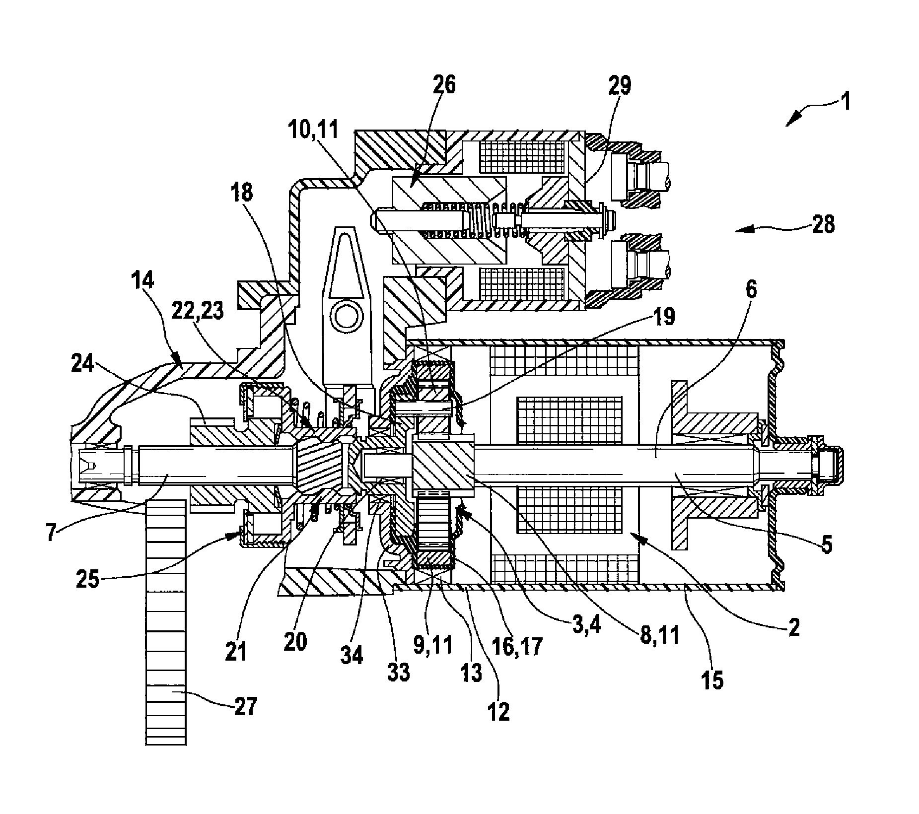
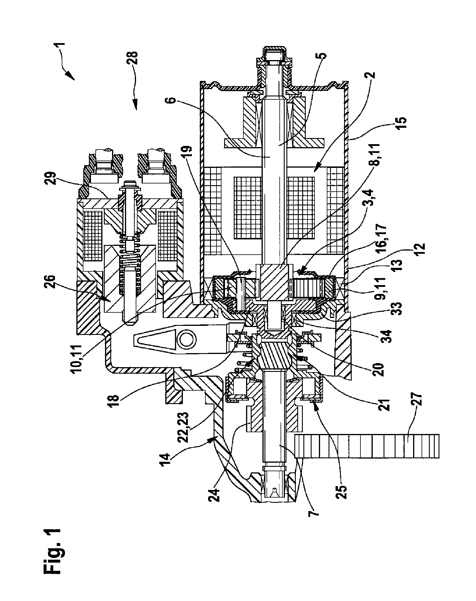
[0014]One development of the invention provides that a
freewheel is assigned to the driven shaft. The
freewheel can prevent the internal combustion engine which has already started from applying a high speed to the drive shaft of the reducing gear and thereby damaging, for example, an electric motor which is connected via said drive shaft. A one-sided transmission torque is therefore implemented by means of the
freewheel, that is to say the torque can be transmitted only from the drive shaft to the driven shaft.
[0015]One development of the invention provides that the reducing gear has a starter
pinion, in particular with helical toothing, which reducing gear can be engaged with a further gearwheel. The starter
pinion is preferably provided on the driven shaft of the reducing gear. There is therefore no intention that the reducing gear or the driven shaft thereof is to be effectively connected on a continuous basis to the internal combustion engine—to which the other gearwheel can be assigned—or to some other device. Instead there is provision that the connection can be interrupted by means of the starter
pinion. It is therefore possible, for example during a starting process of the internal combustion engine, to provide for torque to be transmitted from the drive shaft of the reducing gear to the internal combustion engine, while this connection is interrupted subsequent to the starting process. This is done by means of the starter pinion, which can be engaged with a further gearwheel which is assigned, for example, to the internal combustion engine or to the further device. The starter pinion particularly advantageously has a helical toothing for facilitating
mutual engagement during operation. It is possible, for example, for the freewheel to be assigned to the starter pinion, or for these two elements to be structurally integrated.
[0016]One development of the invention provides at least one damping device which is assigned to the drive shaft and / or the driven shaft and / or the gearwheels. In order to improve the acoustic behavior, the reducing gear can be equipped with at least one damping device. The damping device serves to considerably reduce the vibration excitations which are caused, for example, by the internal combustion engine. Such a device can therefore make a significant contribution to reducing the
noise level and the vibrations. In this context, the at least one damping device is assigned to the drive shaft and / or the driven shaft and / or the gearwheels of the reducing gear. The damping device is advantageously arranged between the reducing gear and the internal combustion engine or the further device, with the result that vibrations are already damped before the reducing gear is reached. This is beneficial for the service life of the gearwheels. A further improvement in the acoustic properties can be obtained by using multiple damping devices.

