Spiral lifting shaft and stirring mill

A technology of screw hoisting and grinding mill, applied in grain processing and other directions, can solve the problems of insufficient grinding, affecting the use of mineral powder, reducing the uniformity of particle size of mineral powder, etc., to improve grinding adequacy, prolong continuous grinding process, The effect of high particle size uniformity

Pending Publication Date: 2018-10-16
西双版纳海邦科技(集团)有限公司
View PDF9 Cites 2 Cited by
  • Summary
  • Abstract
  • Description
  • Claims
  • Application Information

AI Technical Summary

Problems solved by technology

At present, there is still insufficient grinding during the grinding process of ore. Insufficient grinding will reduce the uniformity of the particle size of the mineral powder, which will affect the subsequent use of the mineral powder.

Method used


Image

  • Spiral lifting shaft and stirring mill
  • Spiral lifting shaft and stirring mill
  • Spiral lifting shaft and stirring mill

Examples


Embodiment

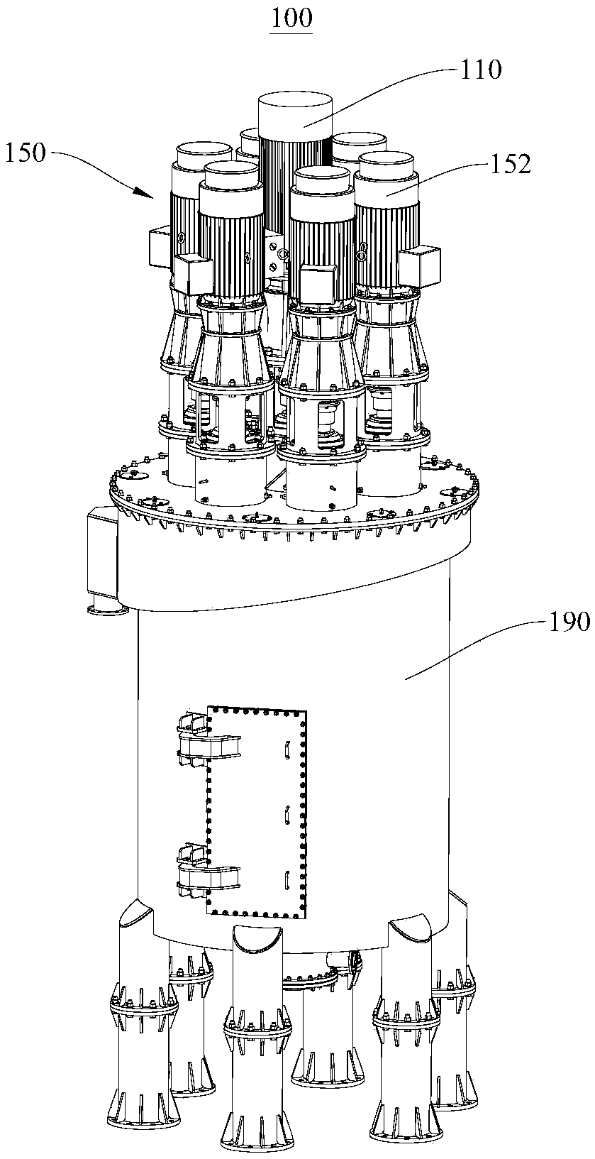
[0037] Please refer to figure 1 , figure 1 A schematic diagram of the structure of the stirred mill 100 is shown. This embodiment provides a stirring mill 100, which mainly utilizes the stirring motion of the grinding medium to produce impact, shearing, and grinding effects, so as to achieve the purpose of crushing materials.

[0038] The stirred mill 100 mainly includes a screw lift shaft 110 , a stirring assembly 150 and a barrel body 190 . Both the stirring assembly 150 and the helical lifting shaft 110 are located in the barrel main body 190 . Such as figure 1 As shown, both the screw lifting shaft 110 and the stirring assembly 150 are arranged to be partly located inside the cylinder main body 190 and partially located outside the cylinder main body 190 . The part located outside the cylinder main body 190 is convenient for transmission connection with driving equipment such as a motor, so that the screw lifting shaft 110 and the stirring assembly 150 can rotate.

[...


PUM


Abstract

The invention provides a spiral lifting shaft and a stirring mill, and relates to the field of milling equipment. The spiral lifting shaft comprises a first rotating shaft and a blade arranged aroundthe first rotating shaft in a spiral mode; a baffle is arranged on one side, away from the first rotating shaft, of the blade; and the first rotating shaft drives the blade connected with the first rotating shaft to rotate together in the rotating process of the first rotating shaft, so that the material at the bottom of the stirring mill gradually rises along the spiral blade, the material movesfrom bottom to top along the spiral blade constantly, so that the material at the bottom obtains an opportunity to be milled more fully, and the milling adequacy of the material at bottom is greatly improved. When the material rises along the blade, the baffle can prevent a large amount of material from spilling from the edge of the blade, so that the material rises to the top end of the blade, the contact time between the material and the milling medium is extended, and the continuous milling process of the material is prolonged; and the milling adequacy of the material can be further improved through continuous milling of the material.

Description

technical field [0001] The invention relates to the field of grinding equipment, in particular to a spiral lifting shaft and a stirring mill. Background technique [0002] The stirring mill is a device that uses a stirring device to move the grinding medium to produce impact, shear, and grinding effects, thereby crushing materials. Conventional mills rely on the movement of the cylinder to drive the movement of the grinding medium, and the input power of the stirring mill is directly used for the rotation of the stirring mechanism to make the grinding medium move and crush the material, so its energy efficiency is higher than that of conventional mills and vibration mills. Agitator mills can be batch or continuous. According to the shape of the cylinder, it can be divided into groove type, ring type, vertical type and other types. [0003] Stirring mill is suitable for grinding various ores and other materials, and is widely used in mineral processing, building materials a...

Claims


Application Information

Patent Timeline
Patent Type & Authority Applications(China)
IPC IPC(8): B02C17/10B02C17/16B02C17/18B02C17/24
CPCB02C17/10B02C17/163B02C17/18B02C17/24
Inventor 郭九阳
Owner 西双版纳海邦科技(集团)有限公司
Why Eureka
Try Eureka