
Combined cutter moving type numerically controlled lathe

A CNC lathe and composite technology, applied in the field of CNC lathes, can solve the problems of increasing the labor intensity of the staff, affecting the drilling speed of the workpiece, reducing the processing efficiency of the workpiece, etc., so as to improve the drilling speed, reduce the labor intensity, and improve the processing efficiency. Effect

Inactive Publication Date: 2018-10-16
莆田市多迪贸易有限公司
View PDF0 Cites 8 Cited by
  • Summary
  • Abstract
  • Description
  • Claims
  • Application Information

AI Technical Summary

Problems solved by technology

[0003] In view of this, the embodiment of the present invention provides a compound-type CNC lathe to improve the existing clamps for drilling of CNC lathes, which can only clamp workpieces of one shape. When it is necessary to clamp workpieces of other shapes, it is necessary to replace the clamping device, which increases the labor intensity of the staff and affects the drilling speed of the workpiece, resulting in a decrease in the processing efficiency of the workpiece.

Method used


Image

  • Combined cutter moving type numerically controlled lathe
  • Combined cutter moving type numerically controlled lathe
  • Combined cutter moving type numerically controlled lathe

Examples


Embodiment

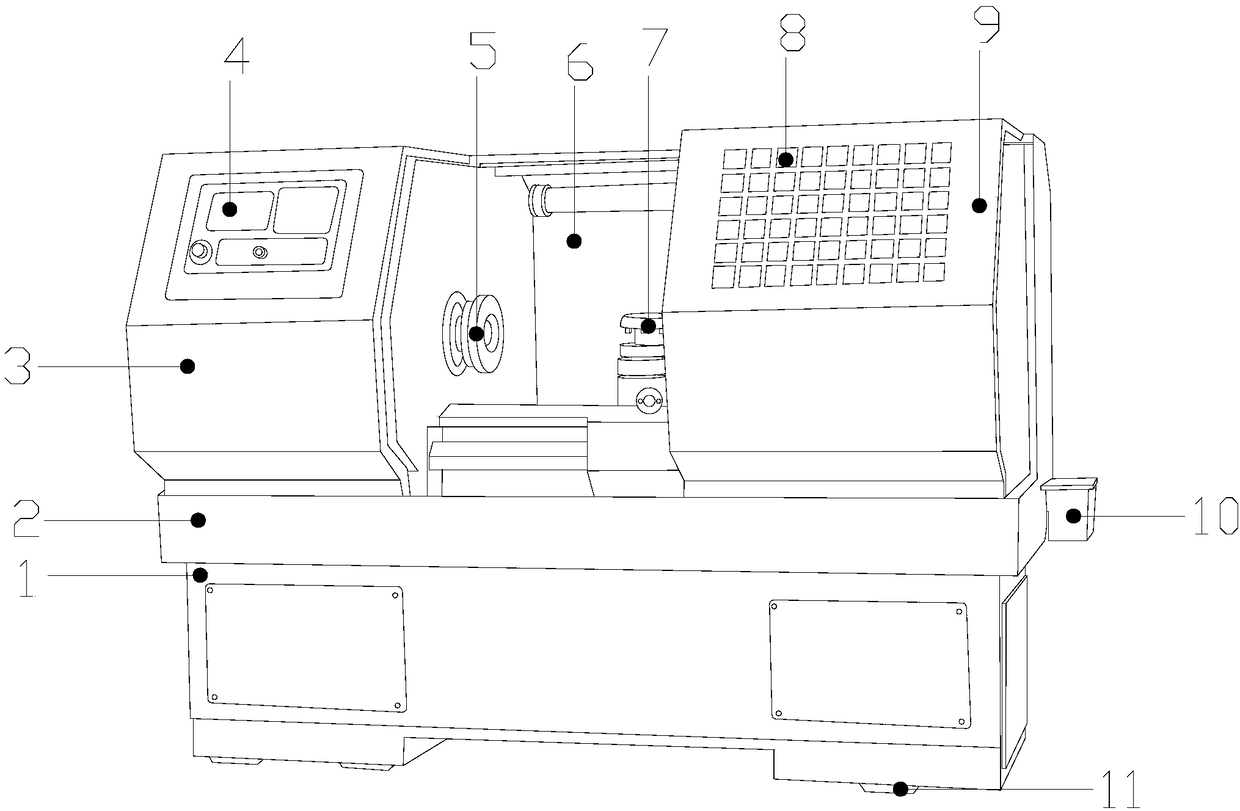
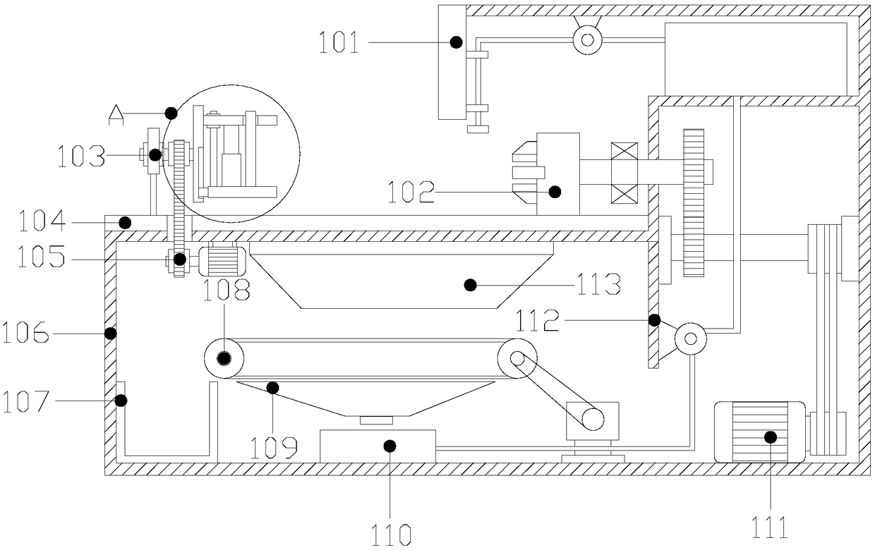
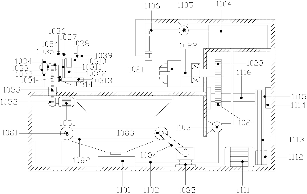
[0022] Such as Figure 1-Figure 5 As shown, the present invention provides a compound type CNC lathe, the structure of which includes an automatic positioning mechanism 1 for processing, an art line 2, an electric control cabinet 3, a control panel 4, a turntable 5, a processing box 6, a processing table 7, Observation port 8, protective door 9, lubricating oil pump 10, fixed feet 11, said fixed feet 11 are provided with more than two and are evenly welded to the bottom of the automatic positioning mechanism 1 for processing, and the automatic positioning mechanism 1 for processing is connected with the artist The lines 2 are all rectangular structures, the left side of the processing box 6 is fixed with an electric control cabinet 3 and the two are welded together, and the bottom of the processing table 7 is fixedly welded to the inside of the processing box 6 and fixedly connected by positioning pins. The protective door 9 is fixedly fastened and installed on the right side ...


PUM


Abstract

The invention discloses a combined cutter moving type numerically controlled lathe. The combined cutter moving type numerically controlled lathe structurally comprises an automatic positioning mechanism for processing, an art line, an electric control cabinet, a control panel, a turntable, a processing box, a processing table top, an observing port, a protecting door, a lubricating oil pump and more than two fixing bottom feet, wherein the more than two fixing bottom feet are uniformly welded to the bottom part of the automatic positioning mechanism for processing; and the automatic positioning mechanism for processing and the art line are both of rectangular structures. According to the combined cutter moving type numerically controlled lathe, a workpiece is continuously efficiently turned and processed while the resource is saved; in case that the workpiece produces a large number of heat due to high-speed turning, cooling liquid in a cooling liquid storing tank can be pumped out through a liquid pumping water pump and then is rapidly sprayed to a high-temperature workpiece to realize rapid cooling through a liquid pumping guide pipe, thus the workpiece temperature can be decreased, and the shortage of performance failure due to excessively high temperature of the workpiece in turning can be avoided; and the processing can be continuously and smoothly carried out.

Description

technical field [0001] The invention relates to a compound type CNC lathe with cutting tool, which belongs to the field of CNC lathes. Background technique [0002] The traditional two-axis CNC lathe is mainly for the processing of circular workpieces, and cannot process special-shaped workpieces such as four-sided and six-sided workpieces. Moreover, the number of installed tools is limited, and the workpieces that require secondary processing (such as side milling, drilling, tapping, boring, etc.) cannot be processed directly, but the workpieces need to be removed for further processing operations, resulting in labor costs and time increases, and greater precision cannot be guaranteed. However, in the existing clamps for drilling of CNC lathes, only a workpiece of one shape can be clamped. When workpieces of other shapes need to be clamped, the clamping device needs to be replaced. It reduces the labor intensity of the staff and affects the drilling speed of the workpiece...

Claims


Application Information

Patent Timeline
Patent Type & Authority Applications(China)
IPC IPC(8): B23B25/00B23Q3/06B23Q7/00B23Q11/00B23Q11/10B23Q1/01
CPCB23B25/00B23Q1/015B23Q3/06B23Q7/00B23Q11/0042B23Q11/0067B23Q11/10
Inventor 郭梅香
Owner 莆田市多迪贸易有限公司
Learn More