Cutter body structure with replaceable turning portion

A replaceable and turning technology, applied in turning equipment, tools for lathes, accessories of toolholders, etc., can solve the problems of high price of machine-clamped turning tools, inability to be widely used, and low machining accuracy, so as to reduce cutting tools. The effect of preparing consumables, novel structure, and improving turning accuracy

Inactive Publication Date: 2018-10-16
江苏切剀刀具有限公司
View PDF0 Cites 0 Cited by
  • Summary
  • Abstract
  • Description
  • Claims
  • Application Information

AI Technical Summary

Problems solved by technology

[0004] The present invention aims at the disadvantages of the current integral turning tool and welding turning tool with low processing precision and relatively large consumables; machine-clamp turning tools are expensive, high in production cost, and cannot be widely used, etc., and propose a replaceable tool body structure for the turning part , this structure can save tool consumables, reduce tool cost, and further improve machining accuracy

Method used


Image

  • Cutter body structure with replaceable turning portion

Examples


Embodiment Construction

[0013] The present invention will be further described below in conjunction with accompanying drawing:

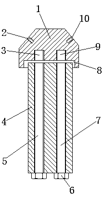
[0014] Such as figure 1 As shown, a replaceable cutter body structure of the turning part includes a handle 4; a left connection deep hole 5 and a right connection deep hole 7 are arranged in the handle 4, and a cutter head 1 is provided at the front end of the handle 4, and the cutter head 1 is provided with a first connecting groove 2 and a second connecting groove 10, and the bottom of the cutter head 1 is provided with a positioning groove 8, and the bottom surface of the positioning groove 8 is provided with a left fastening groove 3 and a right fastening groove 9. One end of the handle 4 is set in the positioning groove 8, and the left connecting deep hole 5 and the right connecting deep hole 7 are provided with a fastener 6, and the head of the fastener 6 is connected to the left fastening groove 3 and the right fastening groove 9 Among them, the end of the knife ha...


PUM


Abstract

The invention discloses a cutter body structure with a replaceable turning portion, and belongs to the technical field of machine tool cutters. The cutter body structure with the replaceable turning portion comprises a cutter handle. A left deep connecting hole and a right deep connecting hole are formed in the cutter handle. A cutter head is arranged at the front end of the cutter handle, a firstconnecting groove and a second connecting groove are formed in the upper portion of the cutter head, a locating groove is formed in the lower portion of the cutter head, and a left fastening groove and a right fastening groove are formed in the groove bottom surface of the locating groove. One end of the cutter handle is arranged in the locating groove. Fasteners are arranged in the left deep connecting hole and the right deep connecting hole, and the heads of the fasteners are connected to the interiors of the left fastening groove and the right fastening groove. The end of the cutter handleis connected with the groove bottom of the locating groove in a closely attached mode. The cutter body structure with the replaceable turning portion is novel in structure and clear in working principle. Compared with a conventional turning tool structure, the cutter body structure with the replaceable turning portion has the advantages that the number of cutter manufacturing consumables is reduced, the machining cost is reduced, the cutter body structure can be used and popularized, the key point lies in the fact that the cutter head can be replaced under the condition that a cutter body does not need to be disassembled when turning is conducted, the cutter head is conveniently replaced, tool setting operation does not need to be conducted, and the turning accuracy is further improved.

Description

technical field [0001] The invention belongs to the technical field of machine tools and relates to a turning tool structure, in particular to a replaceable turning part tool body structure. Background technique [0002] That is, lathe processing, which is a part of mechanical processing. Lathe processing mainly uses turning tools to turn rotating workpieces. Lathes are mainly used to process shafts, disks, sleeves and other workpieces with rotating surfaces, and are the most widely used type of machine tool processing in machinery manufacturing and repair factories. The lathe uses different turning tools or other tools to process various rotating surfaces, such as inner and outer cylindrical surfaces, inner and outer conical surfaces, threads, groove turning grooves, end faces and forming surfaces, etc. The machining accuracy can reach IT8~IT7, and the surface roughness Ra The value is 1.6-0.8. Turning is often used to process single-axis parts, such as straight shafts, g...

Claims


Application Information

Patent Timeline
Patent Type & Authority Applications(China)
IPC IPC(8): B23B27/00
CPCB23B27/00
Inventor 李树金
Owner 江苏切剀刀具有限公司
Why Eureka
Try Eureka