Method and device capable of sufficiently utilizing friction stir welding material
A friction stir and welding material technology, applied in welding equipment, non-electric welding equipment, metal processing equipment, etc., can solve the problems of low utilization rate and large waste of materials, and achieve the effect of improving utilization rate and material utilization rate
- Summary
- Abstract
- Description
- Claims
- Application Information
AI Technical Summary
Problems solved by technology
Method used
Image
Examples
Embodiment 1
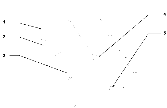
[0034] Such as figure 1 shown.
[0035] A method that can make full use of friction stir welding materials. While completing friction stir welding, a brand new part is manufactured by using the material extruded by the stirring head, so as to achieve the dual purpose of obtaining welding plates and new parts in one friction stir welding. Specific steps are as follows:
[0036] First, use the clamps on the friction stir welding backing plate to fix the plates to be welded by friction stir welding; the clamps set around the backing plate are adjustable, and the clamps are placed on both sides of the backing plate to prevent excessive deformation of the plates during processing. The backing plate is steel plate, titanium alloy plate, tungsten alloy plate or molybdenum alloy plate. Such as figure 1 shown.
[0037] Secondly, a molding die is set at the end of the welding seam path, and the mold is fixed, and the feed port of the mold is opposite to the welding seam; the molding...
Embodiment 2
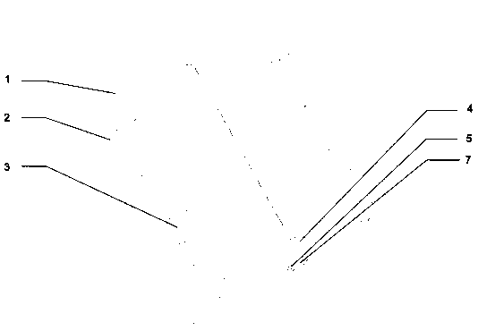
[0041] Such as Figure 2-4 shown.
[0042] A device that can make full use of friction stir welding materials. When the friction stir welding is completed, the material extruded by the stirring head is used to manufacture parts. The device uses the clamp 3 on the friction stir welding backing plate 2 to fix the friction stir welding plate 1 ,Such as figure 2 , 3 And set a set of specific forming molds 5 at the end of the welding seam path, place the plate to be welded on the fixture 3 to fix it, when the stirring head rotates and extends into the seam of the plate to be welded, the temperature of the plate is raised and softened, The extrusion process of the stirring head causes the end of the plate to deform, and a bulge appears. The bulge is squeezed into the forming die 5 at the end, and finally the welded plate 1 and the processed part 7 are obtained by cutting and grinding, such as Figure 4 . In order to facilitate demoulding, the forming mold 5 can be designed as a...
Embodiment 3
[0046] Such as Figure 5-7 shown.
[0047]A device that can make full use of friction stir welding materials, which includes a special mold 5 arranged at the end of the backing plate center direction; as Figure 5 , 6 As shown, the steel backing plate 2 (also can be titanium alloy plate, tungsten alloy plate, molybdenum alloy plate and other metal material plates), such as Figure 5 As shown, the size of the backing plate 2 is 800mm×400mm×30mm; the diameter of the stirring head is 5-100mm; there are adjustable clamps 3 around the backing plate 2, which are placed on both sides of the backing plate to prevent excessive deformation of the plate during processing.
[0048] Such as Figure 5 shown. Before the friction stir welding, place the 3.2mm thick 2024 aluminum alloy plate 1 to be welded on the backing plate 2, and adjust the clamp 3 to clamp the plate so that the end of the joint is aligned with the mold 5, and the mold 5 is a rectangle inside The concave mold of the g...
PUM
| Property | Measurement | Unit |
|---|---|---|
| diameter | aaaaa | aaaaa |
| radius | aaaaa | aaaaa |
Abstract
Description
Claims
Application Information
 - R&D
- Intellectual Property
- Life Sciences
- Materials
- Tech Scout
- Unparalleled Data Quality
- Higher Quality Content
- 60% Fewer Hallucinations
Browse by: Latest US Patents, China's latest patents, Technical Efficacy Thesaurus, Application Domain, Technology Topic, Popular Technical Reports.
© 2025 PatSnap. All rights reserved.Legal|Privacy policy|Modern Slavery Act Transparency Statement|Sitemap|About US| Contact US: help@patsnap.com


