
Mechanical arm for plate installing

A technology of mechanical arms and plates, applied in the directions of manipulators, conveyor objects, transportation and packaging, etc., can solve the problem of lack of mechanical arms for clamping glass installation plates, etc., to achieve easy engagement, easy lifting adjustment, and short production cycle Effect

Inactive Publication Date: 2018-10-16
阜阳市润泰通用机械有限公司
View PDF4 Cites 10 Cited by
  • Summary
  • Abstract
  • Description
  • Claims
  • Application Information

AI Technical Summary

Problems solved by technology

[0005] The purpose of the present invention is to solve the problem of the lack of a mechanical arm for clamping glass installation panels in the prior art, and propose a mechanical arm for panel installation

Method used


Image

  • Mechanical arm for plate installing
  • Mechanical arm for plate installing
  • Mechanical arm for plate installing

Examples


Embodiment 1

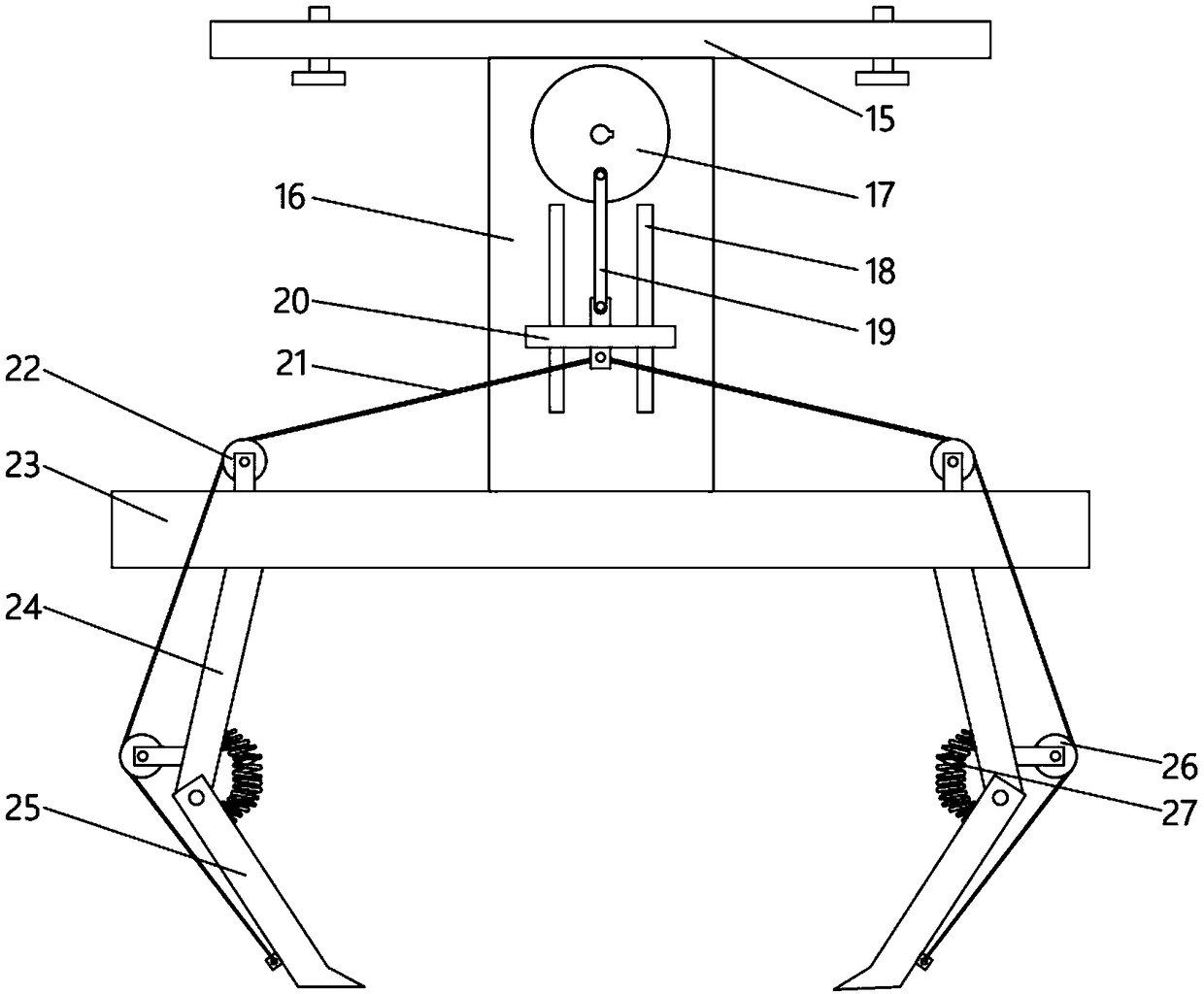
[0021] Embodiment 1: refer to figure 1 , a mechanical arm for plate installation, including a mounting plate 15, the end of the mounting plate 15 away from the hanging plate 8 is fixedly connected with a fixing plate 16, a second reduction motor is installed on the fixing plate 16, and the output shaft of the second reduction motor The wheel disc 17 is sleeved, and the output shaft of the second reduction motor is connected with the wheel disc 17 through an interference fit through a flat key. The interference fit connection process is simple and the connection is stable. One end of the rod 19 away from the wheel disc 17 is rotatably connected with a connecting frame 20, the connecting frame 20 is slidably connected to the fixed plate 16, the fixed plate 16 is provided with a T-shaped groove 18, and the connecting block 20 is fixedly connected with a T-shaped block, and the T Type groove 18 is slidingly connected with T-shaped block, and T-type groove is convenient for install...

Embodiment 2

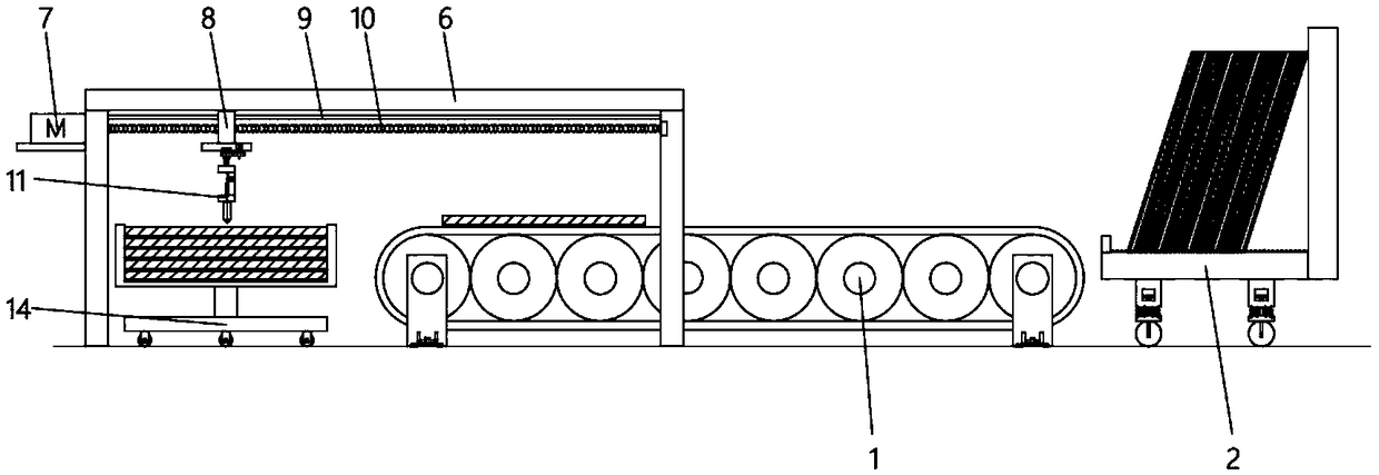
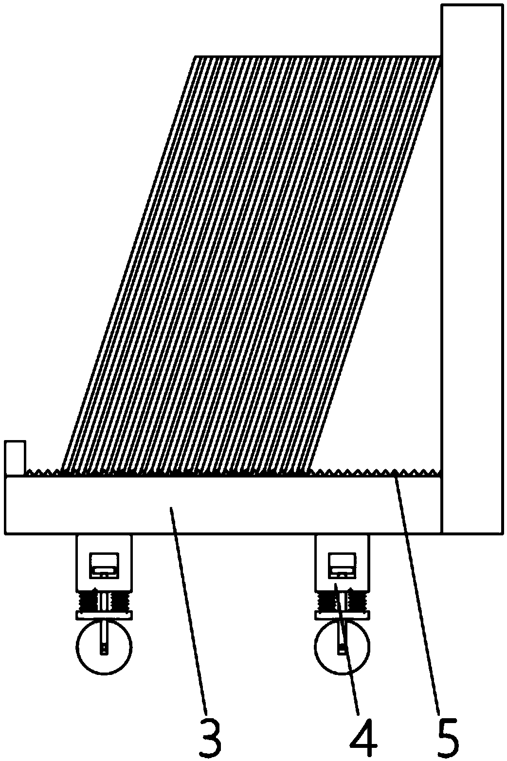
[0022] Embodiment 2: refer to Figure 1-4 , applying the present invention to a fully automatic sheet material installation manipulator device, comprising a sheet material transfer device 1, a gantry frame 6, a first trolley 2 and a second trolley 14, the first trolley 2 includes a The base 3 and the backrest are formed, the upper end of the base 3 is provided with a plurality of sawtooth grooves 5, the bottom end of the base 3 is equipped with a plurality of buffer travel mechanisms 4, and the lower end of the base 3 is slidably connected with a plurality of limit columns, and the limit column The lower end is provided with a roller frame, and a spring shock absorber is provided between the roller frame and the base 3, and each group of roller frames is rotatably connected with rolling wheels, and each rolling wheel is provided with anti-slip lines, and the setting of the buffer traveling mechanism 4 can Buffering and shock absorption prevents the glass from being damaged. Th...


PUM


Abstract

The invention discloses a mechanical arm for plate installing. The mechanical arm comprises an installing plate, a fixing plate is fixedly connected to the end, far away from a lifting plate, of the installing plate, a second gear motor is installed on the fixing plate, an output shaft of the second gear motor is sleeved with a wheel disc, a connecting rod is rotationally connected to the eccentric position of the wheel disc, a connecting support is rotationally connected to the end, far away from the wheel disc, of the connecting rod and is connected to the fixing plate in a sliding manner, asupporting plate is fixedly connected to the end, far away from the installing plate, of the fixing plate, two first fixed pulleys are symmetrically installed on the supporting plate, two first fixing claws are symmetrically ad fixedly connected to the end, far away from the fixing plate, of the supporting plate, and second fixing claws are rotationally connected to the ends, far away from the fixing plate, of the first fixing claws. The mechanical arm is stable in structure, simple in operation, scientific and reasonable in design and short in production period, the mechanical arm can be conveniently lifted and adjusted, and plates can be conveniently clamped.

Description

technical field [0001] The invention relates to the technical field of sheet material installation manipulators, in particular to a mechanical arm used for sheet material installation. Background technique [0002] The robotic arm is the most widely used automatic mechanical device in the field of robotics. It can be seen in industrial manufacturing, medical treatment, entertainment services, military, semiconductor manufacturing, and space exploration. Although their shapes are different, they all have a common feature, that is, they can accept instructions and precisely locate a certain point in three-dimensional (or two-dimensional) space for operation. A manipulator is an automatic operating device that can imitate certain movement functions of the human hand and arm to grab, carry objects or operate tools according to a fixed program. The feature is that various expected operations can be completed through programming, and the structure and performance have both the ad...

Claims


Application Information

Patent Timeline
IPC IPC(8): B23P19/00B65G47/90B25J15/00B25J5/00
Inventor 马东峰万传贺武迎春
Owner 阜阳市润泰通用机械有限公司
Features
  • Generate Ideas
  • Intellectual Property
  • Life Sciences
  • Materials
  • Tech Scout
  • Unparalleled Data Quality
  • Higher Quality Content
  • 60% Fewer Hallucinations
Learn More