
Rain-sewage shunting type rainwater opening structure

A rainwater diversion and rainwater outlet technology, which is applied in the direction of sewage discharge, drainage structures, waterway systems, etc., can solve problems such as the inability to realize rainwater diversion, and achieve the effects of convenient implementation, simple structure, and convenient dredging

Active Publication Date: 2018-10-16
WUXI MUNICIPAL DESIGN INST
View PDF6 Cites 4 Cited by
  • Summary
  • Abstract
  • Description
  • Claims
  • Application Information

AI Technical Summary

Problems solved by technology

[0005] Therefore, those skilled in the art aim at the problem that road gullies cannot realize the initial rainwater diversion, and devote themselves to developing a rainwater diversion type gully with simple structure and convenient implementation.

Method used


Image

  • Rain-sewage shunting type rainwater opening structure
  • Rain-sewage shunting type rainwater opening structure
  • Rain-sewage shunting type rainwater opening structure

Examples


Embodiment 1

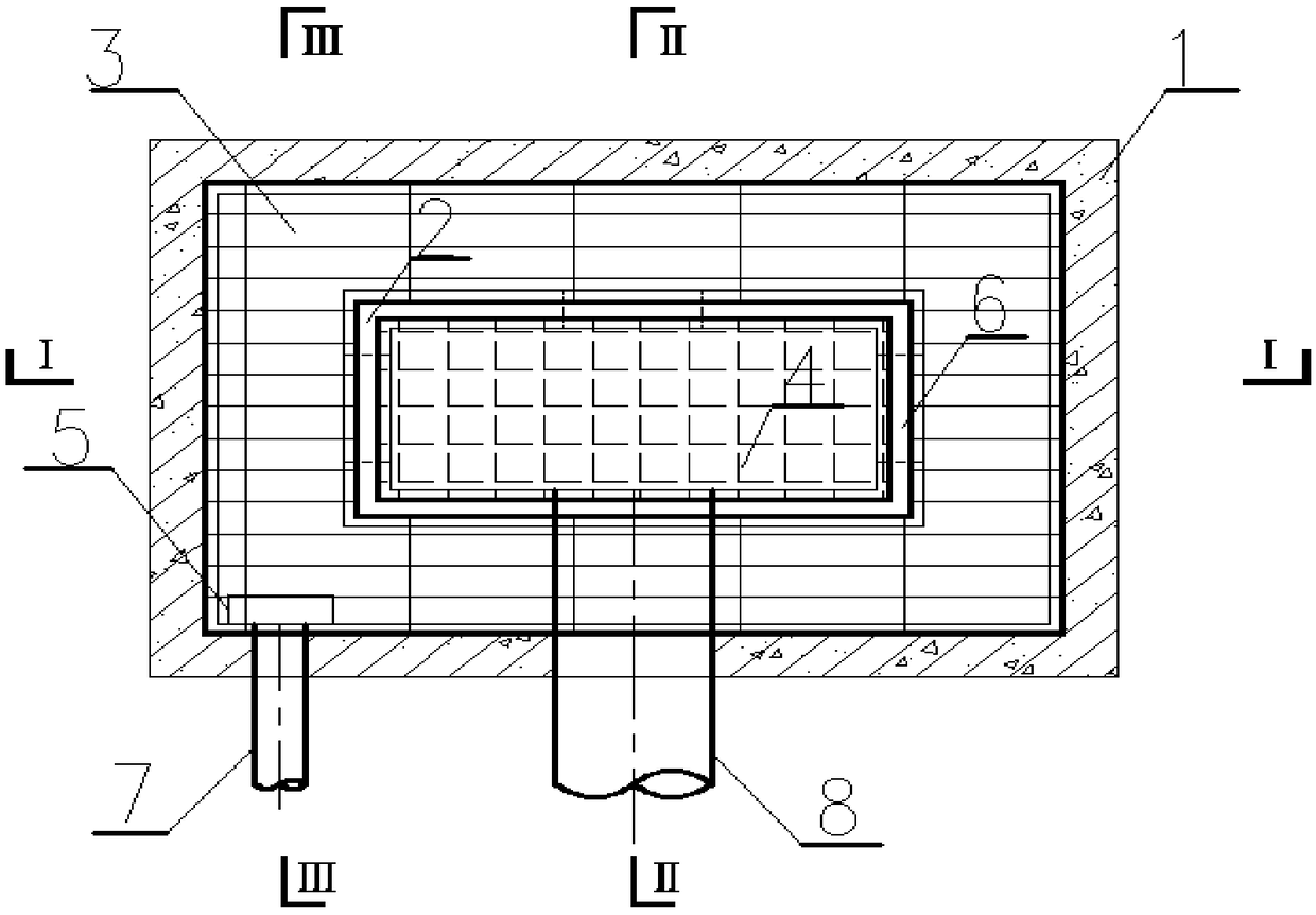
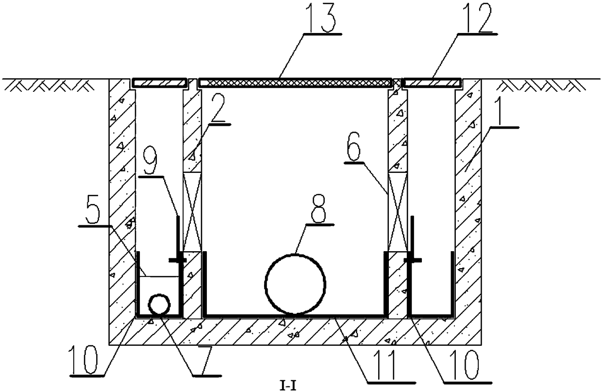
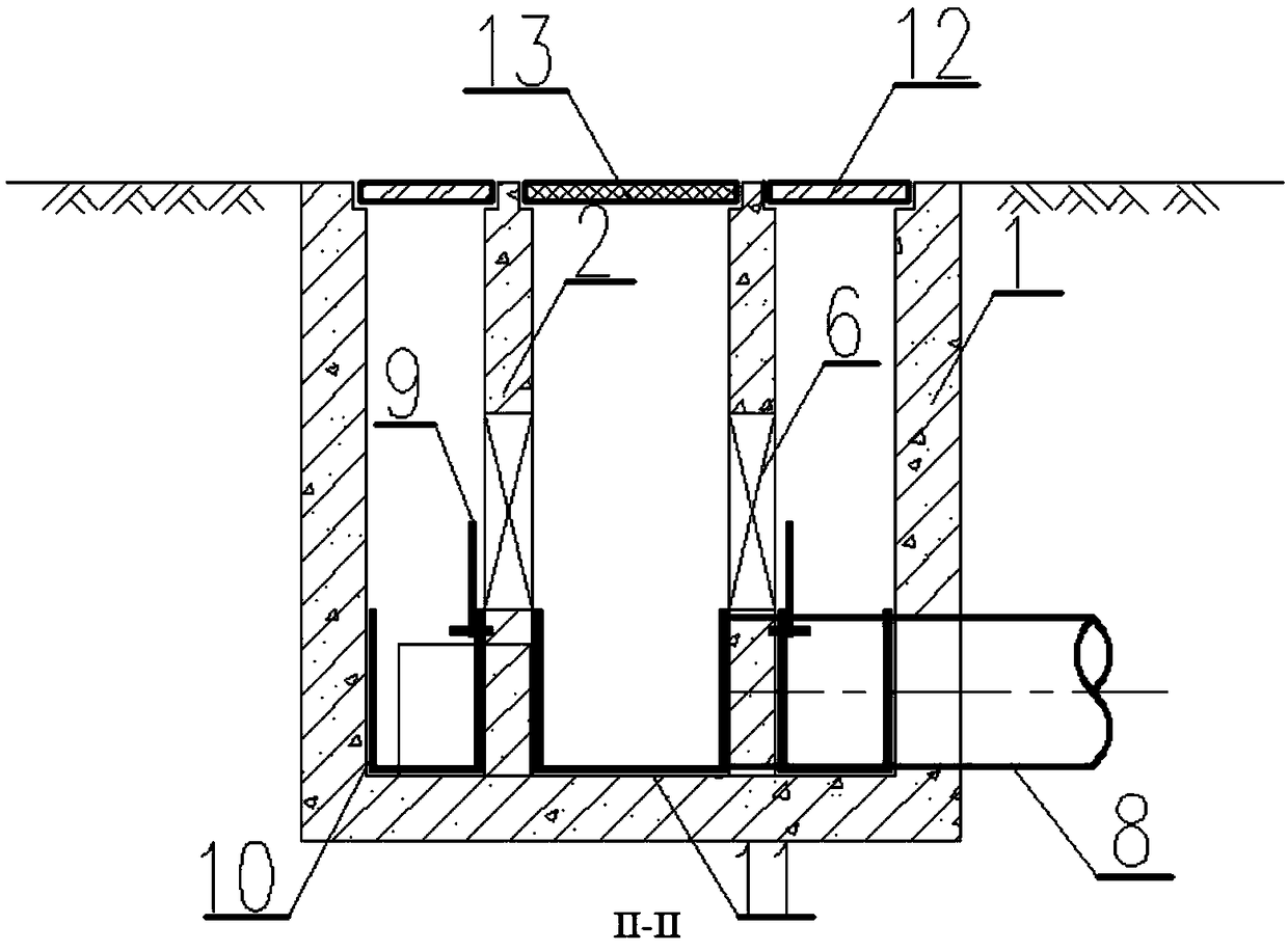
[0050] Simulate the situation where sewage from restaurants and restaurants pours into roadside storm drains. The rectangular ring area 3 is a sewage collection area covered with a rectangular ring cover plate 12 . Sewage is engraved on the cover plate of the rectangular ring. After the sewage is quickly poured into the rectangular ring area 3, the liquid level rises to the liquid level 1. After the sewage is filtered by the filter screen 5, the impurities remain in the rectangular ring dredging bucket 10, and the sewage is discharged into the sewage system through the sewage pipe 7 and finally reaches the Sewage plant treatment and disposal isolates the sewage from flowing into the rainwater system. Rectangular ring dredging bucket 10 can regularly propose dredging.

Embodiment 2

[0052] Simulate the situation of rainwater flowing into the roadside gullies when the initial rainwater is intercepted, see Image 6. In the early stage of rainfall, the initial rainwater first collects into the rectangular ring area 3, and the liquid level continues to rise to the liquid level 1. At this time, the initial rainwater flows to the sewage treatment system through the sewage pipe 7 for treatment, and the initial rainwater, including the pollutants therein, is discarded. flow. As the rainfall increases, the liquid level gradually rises to the liquid level 2 and turns over the adjustable weir plate 9. There are multiple threaded holes at intervals of 20 cm on the weir plate, and the threaded holes cooperate with the screws embedded in the wall to realize Adjustment for different heights.

[0053] And after entering the rectangular area 4 through the water-passing square hole 6, the rainwater is discharged into the rainwater system through the rainwater pipe 8 to c...


PUM


Abstract

The invention discloses a rain-sewage shunting type rainwater opening structure which comprises an inner wall and an outer wall. The inner wall forms a rainwater collecting area, and a sewage storagearea is formed in the space between the outer wall and the inner wall. A sewage cover plate covers the top of the sewage storage area, a sewage dredging bucket, a sewage pipe and a filter screen are arranged in the sewage storage area, and the outlet end of the sewage pipe extends out of the rainwater opening structure. A seal plate rotary shaft is arranged at the bottom of the inlet end of the sewage pipe, a sewage sealing plate is arranged on the seal plate rotary shaft, and an adjustable weir plate is arranged at the upper end of the sewage dredging bucket. A square water via hole is formedin the middle of the inner wall. A clear water cover plate covers the top of the rainwater collecting area, a clear water dredging bucket is arranged in the rainwater collecting area, and a rainwaterpipe is arranged at the bottom of the clear water dredging bucket. The rain-sewage shunting type rainwater opening structure intercepts initial rainwater to the most degree while meeting the road water draining requirement on a road needing initial rainwater interception so as to reduce urban watercourse and lake pollution.

Description

technical field [0001] The invention relates to the technical field of water supply and drainage, in particular to a rainwater diversion type gully structure. Background technique [0002] Urban drainage system consists of rainwater system and sewage system. The rainwater outlet refers to the facility that the pipeline drainage system collects surface water, and the structure that collects rainwater on the rainwater pipeline or combined pipeline, and is composed of water inlet grates, wells and branch pipes. It is the basic unit of the rainwater system. Rainwater from roads, squares and grasslands, and even the roofs of some buildings first flows into the rainwater outlet through the grate, and then flows into rivers or lakes through connecting pipes. The rainwater outlet is the entrance for rainwater to enter the city's underground, an important facility for collecting ground rainwater, and a channel for sending rainwater from the sky directly to the urban river and lake ...

Claims


Application Information

Patent Timeline
Patent Type & Authority Applications(China)
IPC IPC(8): E03F1/00E03F5/04
CPCE03F1/00E03F5/0401E03F5/0404E03F2201/10Y02A20/108
Inventor 薛峰
Owner WUXI MUNICIPAL DESIGN INST
Learn More