Rotary cast steel support method for building steel structure

A supporting method and a technology for structure, applied in the direction of building structure, construction, etc., can solve the problems of increased use and maintenance costs, damage, permanent deformation of structures, etc., to achieve increased use and maintenance costs, wide application range, and extended use The effect of longevity

Inactive Publication Date: 2018-10-16
曹菊平
View PDF1 Cites 0 Cited by
  • Summary
  • Abstract
  • Description
  • Claims
  • Application Information

AI Technical Summary

Problems solved by technology

[0002] In the field of existing building steel structures, the connection between the steel frame and the steel frame and between the steel frame and the column is mostly a hinged structure. When it exceeds a certain value, the structure will have permanent deformation that is difficult to recover, and even the structure will be damaged.
In order to prevent the above-mentioned damage, the upper coupling and the lower coupling of the pin rotating device are respectively connected to the steel frame of the building steel structure. The upper coupling can rotate around the pin installed on the lower coupling. When the frame is subjected to When the external force is consistent with the rotation direction of the upper coupling around the pin shaft, the force can be reduced due to the rotation of the steel frame, thereby avoiding damage to the structure. The role of the pin shaft rotation device is limited because the external force brought by the structure is arbitrary. Yes, there is no fixed direction, so the pin shaft rotation device still cannot perfectly guarantee the safety of the building steel structure. In the prior art, for example, the invention patent with application number 200820124377.8 includes upper support, bolts, springs, hemispherical pads Block, stainless steel plate, lower support, lower support connecting bolts, a hemispherical groove is provided on the bottom surface of the upper support, a stainless steel plate is provided on the connecting surface of the lower support, and a hemispherical groove is provided on the stainless steel plate to connect with the upper support The hemispherical pads matched with the shaped grooves, the upper and lower supports are connected by bolts for installing springs, the lower support is composed of two symmetrical bodies, and the two symmetrical bodies are connected by the connecting bolts of the lower support. Although the structure of the invention Simple, but there are many deficiencies and defects. In the existing equipment, the design of the lower support has defects. The two seesaws of the lower support will contact the upper support when in use and it is easy to cause the upper support to be damaged. The bending or even damage of the hemispherical gasket increases the cost of use and maintenance, increases the working intensity of the construction workers, and easily causes work fatigue for the construction workers. Moreover, the shock absorption effect of the hemispherical gasket is not ideal, and the relative rotation angle is not good. In addition, the lower The connection between the support and the upper support is connected by a compression spring. The connection between the upper support and the lower support is unstable, which may easily cause safety accidents and affect the construction progress and construction quality. In view of these situations, in order to avoid the above technical problems, it is necessary to Provide a method of rotating cast steel support for building steel structures to overcome the defects in the prior art

Method used


Image

  • Rotary cast steel support method for building steel structure
  • Rotary cast steel support method for building steel structure
  • Rotary cast steel support method for building steel structure

Examples


Embodiment Construction

[0020] The following will clearly and completely describe the technical solutions in the embodiments of the present invention with reference to the accompanying drawings in the embodiments of the present invention. Obviously, the described embodiments are only some, not all, embodiments of the present invention. Based on the embodiments of the present invention, all other embodiments obtained by persons of ordinary skill in the art without making creative efforts belong to the protection scope of the present invention.

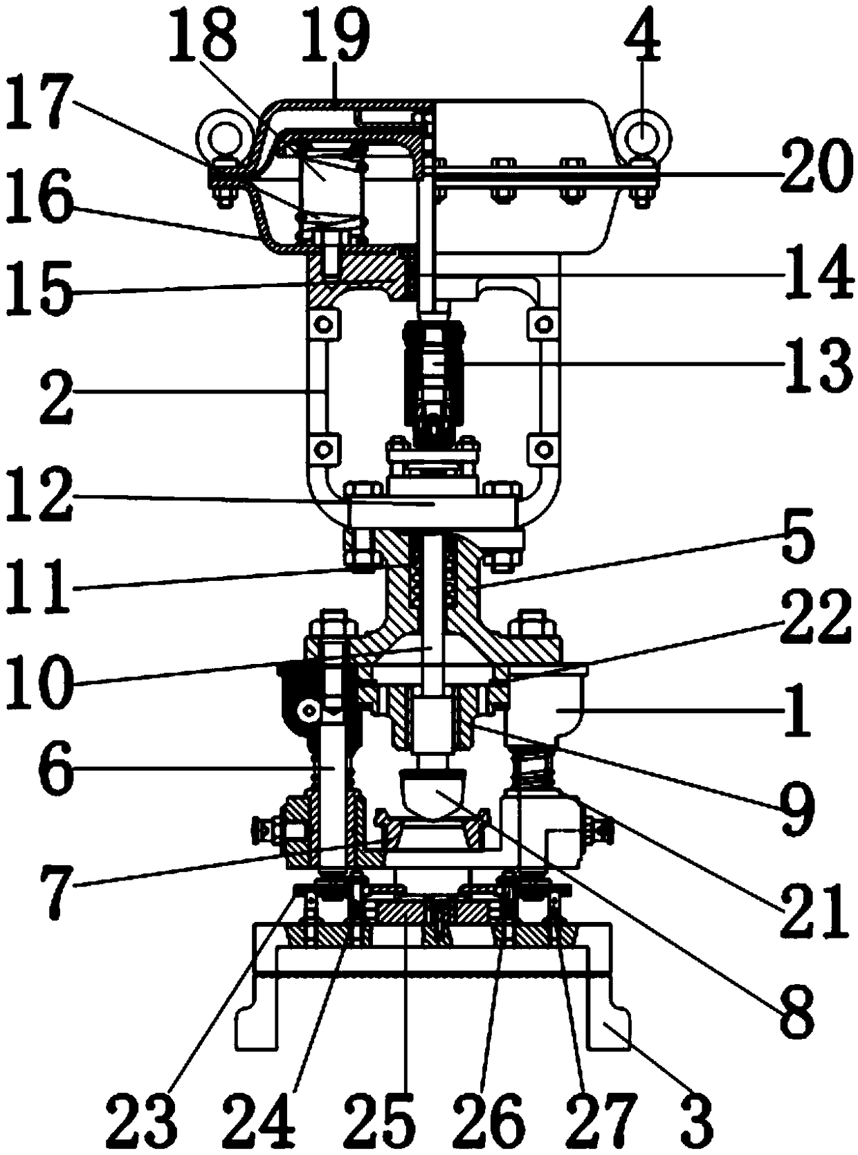
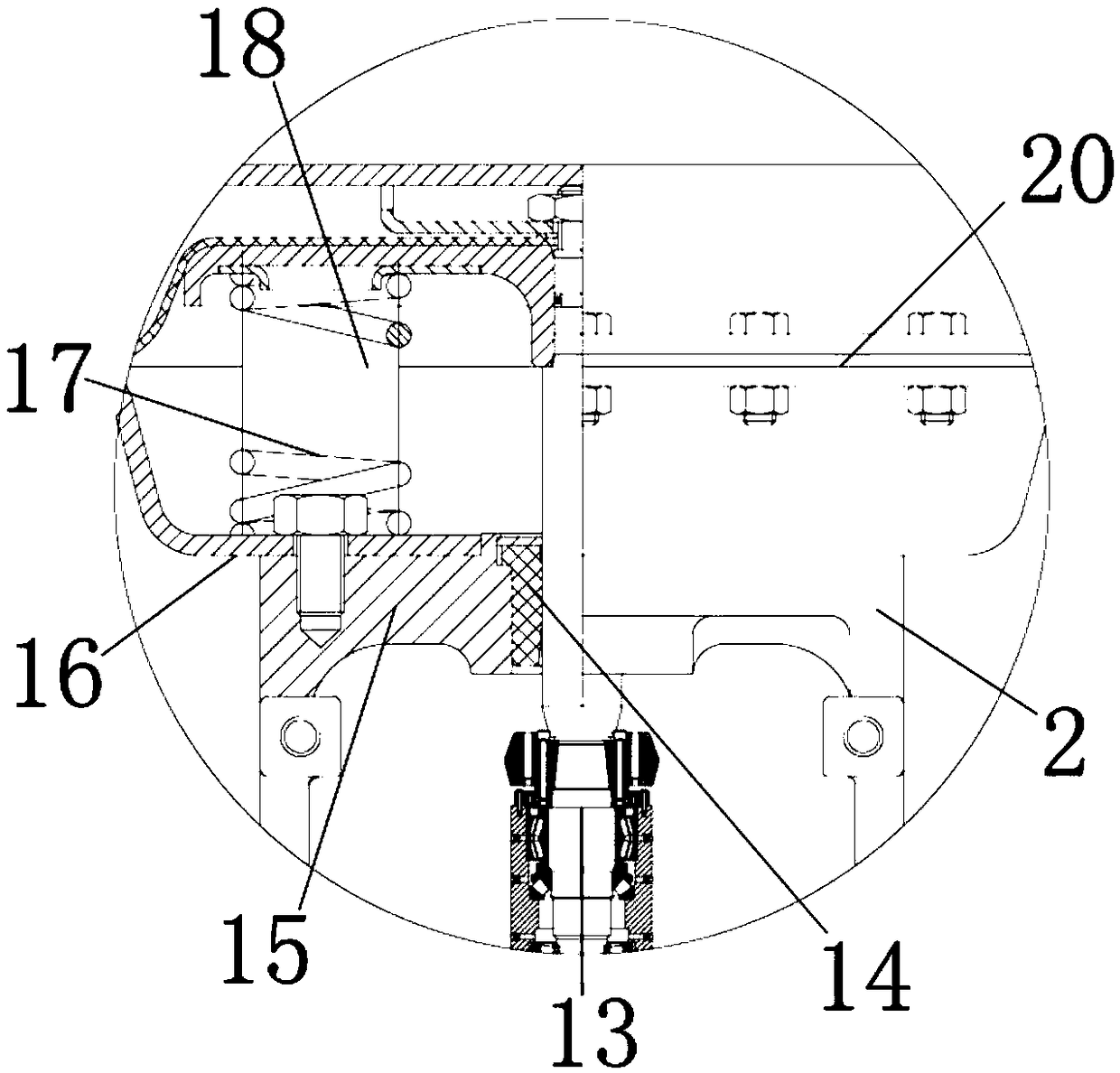
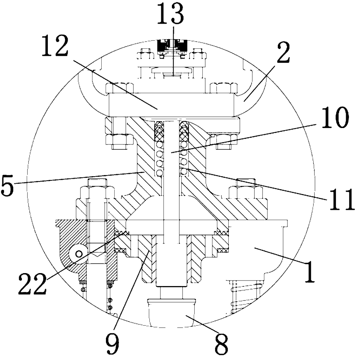
[0021] see Figure 1-4, the present invention provides a technical solution: a rotating cast steel support method for building steel structures, including a lower support 1, the lower support 1 is used to install and fix the hoop 5, the left and right sides of the inner wall of the lower support 1 are A bottom bar 6 is installed for installing and fixing the first compression spring 21, the outer wall of the bottom bar 6 is connected with the outer wall of the...


PUM


Abstract

The invention discloses a rotary cast steel support method for a building steel structure. A lower support seat is used; a bottom rod is arranged at each of the left and right sides of the inner wallof the lower support seat; the outer wall of the bottom rod is connected with the outer wall of the lower support seat; a first compression spring is connected on the outer wall of the bottom rod in asleeving way; the inner wall of the first compression spring is movably connected with the outer wall of the bottom rod; the upper surface of the inner wall of the lower support seat is provided witha rotating seat; the lower surface of the rotating seat is connected with the upper surface of the inner wall of the lower support seat; and a rotating ball is arranged on the inner wall of the rotating seat. A rotary cast steel support seat device for the building steel structure has the advantages that the existing rotary cast steel support seat device for the building steel structure can be more accepted on the market; the product quality of the rotary cast steel support seat device for the building steel structure is improved; the procurement cost of building enterprises is reduced; the resource waste of the rotary cast steel support seat device for the building steel structure is avoided; and the rotary cast steel support seat device for the building steel structure is suitable forbeing popularized and used.

Description

technical field [0001] The invention relates to the technical field of building steel structures, in particular to a rotating cast steel support method for building steel structures. Background technique [0002] In the field of existing building steel structures, the connection between the steel frame and the steel frame and between the steel frame and the column is mostly a hinged structure. When it exceeds a certain value, the structure will have permanent deformation that is difficult to recover, and even the structure will be damaged. In order to prevent the above-mentioned damage, the upper coupling and the lower coupling of the pin rotating device are respectively connected to the steel frame of the building steel structure. The upper coupling can rotate around the pin installed on the lower coupling. When the frame is subjected to When the external force is consistent with the rotation direction of the upper coupling around the pin shaft, the force can be reduced du...

Claims


Application Information

Patent Timeline
Patent Type & Authority Applications(China)
IPC IPC(8): E04B1/36
CPCE04B1/36
Inventor 曹菊平
Owner 曹菊平
Why Eureka
Try Eureka