
A method for star sensor temperature field measurement and pointing temperature drift compensation

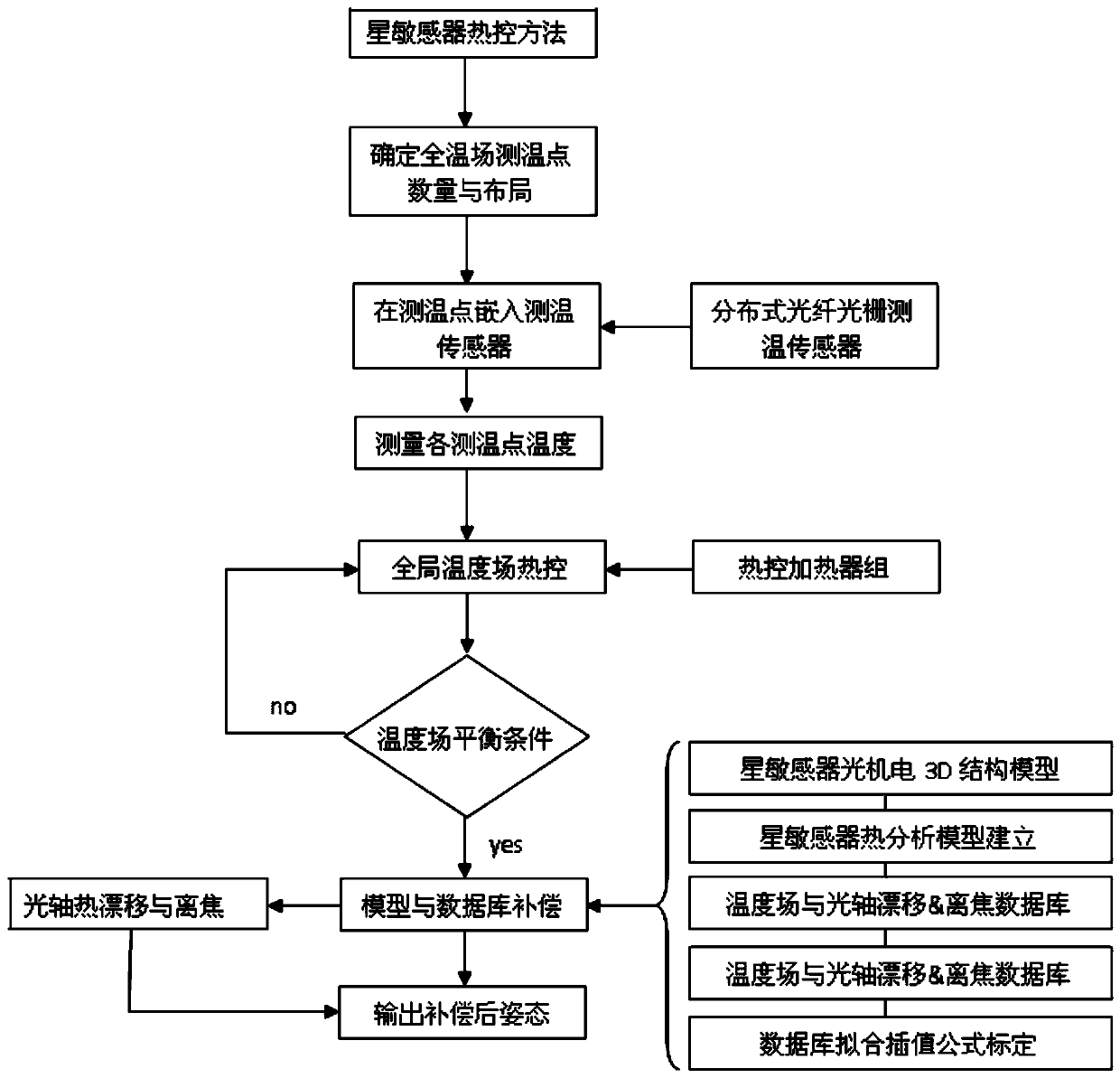
A star sensor and temperature drift compensation technology, which is applied in the direction of measuring heat, measuring devices, and aerospace vehicle guidance devices, can solve the problem of in-orbit thermal optical axis drift that cannot be corrected, and achieve the effect of improving the accuracy of attitude measurement

Active Publication Date: 2019-12-20
BEIJING INST OF CONTROL ENG
View PDF6 Cites 0 Cited by
  • Summary
  • Abstract
  • Description
  • Claims
  • Application Information

AI Technical Summary

Problems solved by technology

[0006] The problem solved by the technology of the present invention is: to overcome the deficiency that the on-orbit thermal optical axis drift cannot be corrected in the existing star sensor technology, and propose a temperature field measurement and pointing temperature drift compensation method of the star sensor, which reduces the optical axis of the star sensor. The low frequency error caused by thermal drift improves the measurement accuracy of the star sensor

Method used


Image

  • A method for star sensor temperature field measurement and pointing temperature drift compensation

Examples


Embodiment

[0034] The main technical indicators of a known star sensor are as follows:

[0035] Accuracy: 0.3″(3σ), optical axis pointing; σ is the standard deviation;

[0036] 2″(3σ), vertical optical axis pointing;

[0037] 0.3″(3σ) (maximum drift of thermo-optic axis due to temperature field change);

[0038] Focal length: 300mm

[0039] Field of view: 2.2° (circular field of view)

[0040] Data update rate: ≥50Hz

[0041] Weight: no more than 5Kg

[0042] According to the present invention, the thermal control method of this star sensor is as follows:

[0043] Step 1: First, use commercial professional software, such as SolidEdge, Nastran, Patran, etc. to establish a three-dimensional diagram of the optical-mechanical structure of the star sensor, and establish a thermal analysis finite element based on the optical-mechanical and circuit design results of the star sensor that can characterize the imaging performance changes of the optical system. Meta-model, using mature therma...


PUM


Abstract

The invention discloses a method for temperature field measurement and directional temperature drift compensation of star sensors. The method comprises the following steps that 1, optical axis drift distances and hot defocus distances of multiple star sensors under distribution of a set working temperature field are calculated; 2, according to calculation results in step 1, the number and distribution of least temperature measurement points which can sense the optical axis drift distances and the hot defocus distances are determined; 3, multiple heaters are arranged in advance according to a model established in step 1 and a temperature measurement point layout determined in step 2, and the number and distribution of the temperature measurement points are calculated and analyzed; 4, a mathematic fitting formula of the optical axis drift distances and the hot defocus distances of multiple similar temperature field sample areas is obtained, and the optical axis drift distance and the hotdefocus distance of a current value of the changed temperature field are calculated; 5, through testing calibration of the temperature field, the mathematic fitting formula of the optical axis driftdistances and the hot defocus distances in step 4 is corrected; 6, compensation quantities of directional measurement data of optical axes of the star sensors are calculated. According to the method,the low-frequency errors caused by hot drift of the optical axes of the star sensors are reduced.

Description

technical field [0001] The invention relates to a global temperature measurement and control method of a star sensor, which belongs to the design field of star sensors for space attitude measurement. Background technique [0002] According to the existing literature, the current method of overcoming the thermal influence of the star sensor is mainly realized from the athermalization design and controlling the temperature of the heating point. [0003] The athermalization design is mainly aimed at the star point imaging quality stability design for the optical system of the star sensor or the mounting bracket for temperature changes. Specifically, the optical system and optical structure have thermal expansion and contraction effects, which will cause deformation of optical parts and structural parts and changes in the thermo-optic constants of optical materials, resulting in changes in optical imaging quality, mainly in thermal defocus and like thermal drift. The goal of t...

Claims


Application Information

Patent Timeline
Patent Type & Authority Patents(China)
IPC IPC(8): G01K11/32B64G1/36
CPCB64G1/361G01K11/3206
Inventor 郝云彩余成武陈建峰梁士通
Owner BEIJING INST OF CONTROL ENG
Learn More