Resistance-capacitance box with AC switch indication circuit operating state monitoring

A technology that represents the circuit and working state, applied in the direction of electronic circuit testing, measuring electricity, measuring devices, etc., can solve problems such as blanks, and achieve the effect of reducing safety pressure, ensuring driving safety, and improving labor productivity

Pending Publication Date: 2018-10-16
柳州和利时科技有限责任公司
View PDF6 Cites 0 Cited by
  • Summary
  • Abstract
  • Description
  • Claims
  • Application Information

AI Technical Summary

Problems solved by technology

[0003] The purpose of the present invention is to provide a resistance-capacitance box with an AC switch indication circuit working state monitoring, which can solve the state monitoring and signal analysis of elements such as resistance, capacitance, diodes, cable lines, etc. that affect the working quality of the indication circuit. It is still a blank problem to determine the position of the turnout by means of

Method used


Image

  • Resistance-capacitance box with AC switch indication circuit operating state monitoring
  • Resistance-capacitance box with AC switch indication circuit operating state monitoring

Examples


Embodiment 1

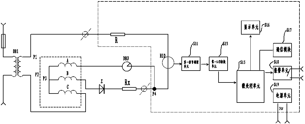
[0013] figure 1 The shown RC box with AC switch indicating circuit working status monitoring has a resistance loop, and the resistance loop has a resistor R, and one end of the resistor R passes through the first current sensor H10 and connects with the outside of the RC box through the first terminal respectively. One end of the external resistor Rx is connected to one end of the relay DBJ, the other end of the external resistor Rx is connected to the cathode of the diode Z, the anode of the diode Z is connected to the B-phase winding of the switch motor, and the other end of the relay DBJ is connected to the A-phase winding of the switch motor , the C-phase winding of the turnout motor is connected to one end of the secondary of the transformer DB1, and the three-phase winding of the turnout motor is connected in a Y shape; the other end of the resistor R is connected to the other end of the secondary of the transformer DB1 through the second terminal, and the first current ...

Embodiment 2

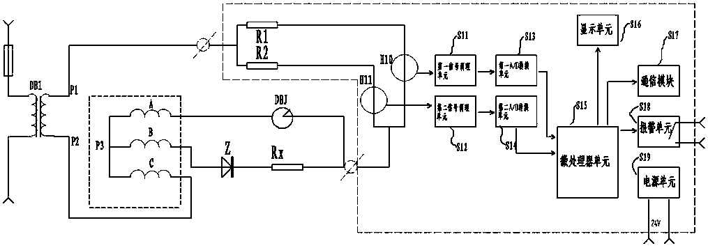
[0023] figure 2 As shown in the RC box with an AC turnout indicating circuit working status monitoring, there are two resistance circuits, and each resistance circuit has a resistance, which are respectively the first resistance R1 and the second resistance R2, and one end of the first resistance R1 After being connected in parallel with the second resistor R2, it is connected to one end of the secondary side of the transformer DB1 through the third terminal, and the other end of the first resistor R1 and the other end of the second resistor R2 respectively pass through the first current sensor H10 and the second current sensor H11 After parallel connection, connect one end of the external resistance Rx outside the RC box through the fourth terminal, the other end of the external resistance Rx is connected to the cathode of the diode Z, the anode of the diode Z is connected to the B-phase winding of the switch motor, and one end of the relay DBJ It is connected to the A-phase...


PUM


Abstract

The invention discloses a resistance-capacitance box with AC switch indication circuit operating state monitoring. The box comprises a resistance loop; the resistance loop comprises a resistor; one end of the resistor is connected to a first terminal through a first current sensor, the other end of the resistor is connected to a second terminal, and a signal of the first current sensor is sent bya first A / D conversion unit to a microprocessing unit after signal conditioning by a first signal conditioning unit. The resistance-capacitance boxcan solve the problem that monitoring the states of elements such as resistors, diodes, and cable lines which affect the working quality of an AC switch indication circuit , and determining the position of a switch by signal analysis are still vacant.

Description

technical field [0001] The invention relates to the technical field of railway signal equipment, in particular to a resistance-capacitance box with an AC switch indicating circuit working state monitoring. Background technique [0002] With the rapid development of my country's railways, the requirements for the safe and efficient operation of railways are getting higher and higher. Railway signal equipment plays a very important role in the entire railway operation. A small fault may disrupt the traffic order and ensure safety. Not guaranteed. At present, the maintenance of railway signal equipment generally adopts the method of regular inspection and replacement, but the status during operation is unknown, and because there are many types and quantities of railway signal equipment in the mechanical room, even if the equipment fails, it is difficult to find , which greatly reduces the efficiency of fault handling. The railway turnout display circuit is used to reflect the ...

Claims


Application Information

Patent Timeline
Patent Type & Authority Applications(China)
IPC IPC(8): G01R31/28G01R19/25
CPCG01R19/25G01R31/2836G01R31/2843
Inventor 覃研陆
Owner 柳州和利时科技有限责任公司
Why Eureka
Try Eureka