
Cross winding type coupling device for wireless electric energy transmission of rotary device

A technology for wireless power transmission and rotating equipment, applied in circuit devices, battery circuit devices, transportation and packaging, etc., can solve problems such as contact surface wear, overheating, poor contact, etc., achieve high quality factor Q value, improve system efficiency, Effect of Coil Loss Reduction

Inactive Publication Date: 2018-10-16
HARBIN INST OF TECH
View PDF4 Cites 2 Cited by
  • Summary
  • Abstract
  • Description
  • Claims
  • Application Information

AI Technical Summary

Problems solved by technology

[0003] Rotating equipment cannot directly use cables for power transmission, because the cables will be entangled when they are rotating, which will damage the power supply cables and cause power interruptions
At present, rotating equipment mainly relies on conductive slip rings for power transmission, and slip rings are powered by brush contact. Therefore, after working for a long time, the contact surface is severely worn, the contact resistance becomes larger, and local overheating occurs, resulting in poor contact or contact separation. It greatly reduces the reliability of the power supply of rotating equipment and reduces the service life of slip rings, which may seriously cause major accidents, and the replacement of slip rings will consume a large cost

Method used


Image

  • Cross winding type coupling device for wireless electric energy transmission of rotary device
  • Cross winding type coupling device for wireless electric energy transmission of rotary device
  • Cross winding type coupling device for wireless electric energy transmission of rotary device

Examples


Embodiment Construction

[0039] It should be noted that, in the case of no conflict, the embodiments of the present invention and the features in the embodiments can be combined with each other.

[0040] The present invention will be described in detail below with reference to the accompanying drawings and examples.

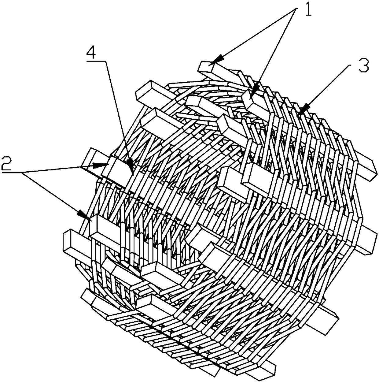
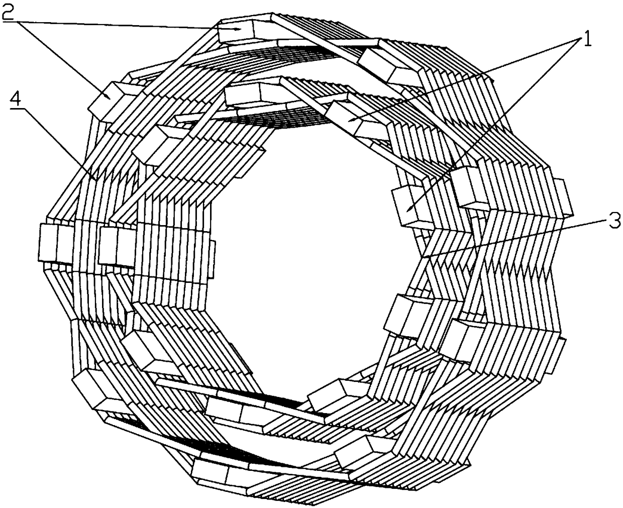
[0041] Such as figure 1 As shown, a cross-wound coupling device for wireless power transmission of rotating equipment includes a power supply core and a power supply coil. The power supply cores are all square bar cores, and the power supply cores include multiple A primary side magnetic core 1 and a plurality of secondary side magnetic cores 2, the plurality of primary side magnetic cores 1 and the plurality of secondary side magnetic cores 2 are all skeleton core structures formed according to a circular array, The positions of the primary side magnetic core 1 and the secondary side magnetic core 2 of each place of the skeleton type magnetic core structure are all opposite, and the de...


PUM


Abstract

The invention provides a cross winding type coupling device for wireless electric energy transmission of a rotary device. The cross winding type coupling device comprises a power-supply magnetic coreand power-supply coils, wherein the power-supply magnetic core is a square strip shaped magnetic core and comprises multiple primary side magnetic cores and multiple secondary side magnetic cores, themultiple primary side magnetic cores and the multiple secondary side magnetic cores are of framework-type magnetic core structures defined by circumferential arrays, the power-supply coils include aprimary side coil and a secondary side coil, the primary side coil and the secondary side coil are coaxially nested and are formed by winding wires around the respective magnetic cores in a cross winding way, the framework-type magnetic core structures defined by the multiple primary side magnetic cores are connected with a fixed end, and the framework-type magnetic core structures defined by themultiple secondary side magnetic cores are connected with a rotary end, so that the mode is formed that a fixed power supply device supplies power for a rotary device; by adopting reverse arrangement,the mode is formed that the rotary power supply device supplies power for the fixed power. The cross winding type coupling device is safe and reliable and can achieve stable and wireless electric energy transmission in a 360-degree rotation range.

Description

technical field [0001] The invention belongs to the technical field of wireless power transmission, and in particular relates to a cross-winding coupling device for wireless power transmission of rotating equipment. Background technique [0002] Due to the wireless power transmission technology getting rid of the dependence of traditional wired power transmission on wires and other electrical conductors, it avoids various problems caused by the traditional wire direct contact power supply method, such as friction, aging, contact resistance, sparks, etc., and meets special needs. The actual needs of electric occasions are a new form of electric energy transmission, which has the characteristics of non-contact, safety and reliability, and is suitable for some special background applications. [0003] Rotating equipment cannot directly use cables for power transmission, because the cables will be entangled when they are rotating, which will damage the power supply cables and ca...

Claims


Application Information

Patent Timeline
Patent Type & Authority Applications(China)
IPC IPC(8): H01F27/24H01F27/25H01F27/28H01F27/34H01F38/14H02J7/00H02J50/10
CPCH01F38/14H01F27/24H01F27/25H01F27/2823H01F27/34H02J7/025H02J50/10
Inventor 朱春波马冰卿宋凯魏国逯仁贵董帅
Owner HARBIN INST OF TECH
Learn More