Optical network synchronization test method and system

A technology of synchronous testing and optical network, applied in the field of communication, can solve problems such as high requirements for testing conditions, measurement errors, and inconsistency of synchronization reference standards in different places, and achieve the effects of reducing operation and maintenance risks, reducing testing costs, and improving testing accuracy

Active Publication Date: 2020-09-18
CHINA ACADEMY OF INFORMATION & COMM +3
View PDF4 Cites 0 Cited by
  • Summary
  • Abstract
  • Description
  • Claims
  • Application Information

AI Technical Summary

Problems solved by technology

[0004] This application proposes a method and system for optical transport network synchronization testing, which solves the technical problems of measurement errors caused by inconsistencies in the synchronization reference standards in different places in the network synchronization test, and the technical problems of difficult testing due to high requirements for the test conditions of the source and sink nodes used for testing

Method used


Image

  • Optical network synchronization test method and system
  • Optical network synchronization test method and system
  • Optical network synchronization test method and system

Examples


Embodiment Construction

[0023] In order to make the purpose, technical solution and advantages of the present application clearer, the technical solution of the present application will be clearly and completely described below in conjunction with specific embodiments of the present application and corresponding drawings. Apparently, the described embodiments are only some of the embodiments of the present application, rather than all the embodiments. Based on the embodiments in this application, all other embodiments obtained by persons of ordinary skill in the art without making creative efforts belong to the scope of protection of this application.

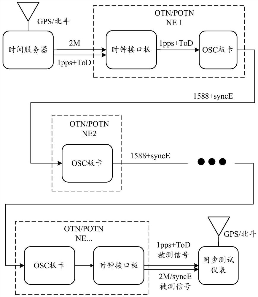
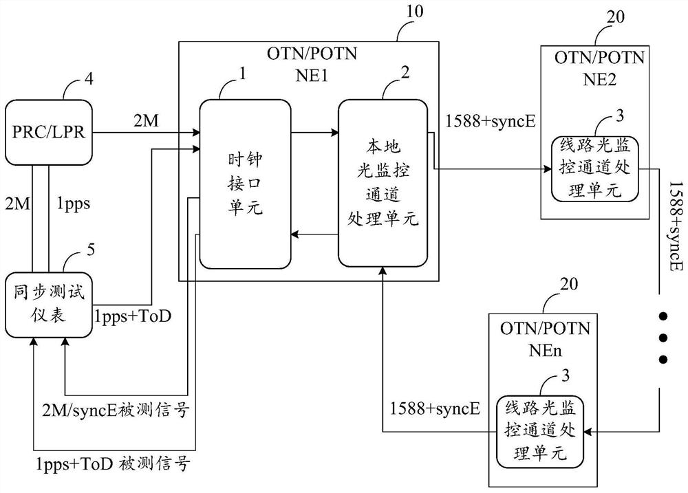
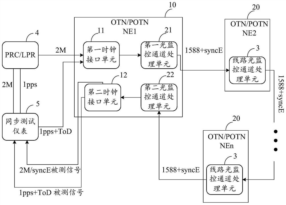
[0024] The technical key point of the present invention is that in the optical network processed by the distributed optical monitoring channel, especially on the OTN / POTN equipment, through the bidirectional optical monitoring channel processing unit and the synchronous interface unit, the IEEE1588 standard can be completed at a single site System loo...


PUM


Abstract

The invention discloses an optical network synchronization testing method and system, and solves a problem that the synchronization references of different places are not consistent. The system comprises a clock interface unit, an optical monitoring channel processing unit, a clock reference source, and a synchronization testing instrument. The method comprises the steps: generating a frequency reference signal by using a clock reference source, generating a time reference signal as an external synchronization signal by using the synchronization testing instrument, inputting the external synchronization signal into a clock interface unit of a local network element, generating a line synchronization signal, then packaging the signal to an optical monitoring channel signal, and transmittingthe signal to a line network element; setting the line network element, and transmitting the line synchronization signal through a line optical monitoring channel processing unit until the line synchronization signal is transmitted to a local optical monitoring channel processing unit; setting the local optical monitoring channel processing unit to recover the line synchronization signal from theoptical monitoring channel signal, then recovering the external synchronization signal as a tested signal by the clock interface unit, and inputting the tested signal into the synchronization testinginstrument. The method improves the accuracy, avoids the constraint of onsite conditions, and reduces the cost.

Description

technical field [0001] The present application relates to the communication field, in particular to a method and system for synchronous testing of an optical transport network. Background technique [0002] In the optical network, although the optical transport network (such as OTN / POTN) that adopts asynchronous working mode does not need frequency synchronization and time synchronization itself, it must carry frequency and time synchronization signals as a bearer network. On the one hand, it needs to communicate with other bearers The network performs synchronous signal docking, and on the other hand, it needs to provide support for the timing link organization of the synchronous network. [0003] Optical network system frequency synchronization and time synchronization live network test play a vital role in performance verification, project commissioning, and later maintenance. However, the technical problems in the current network test method are: on the one hand, the so...

Claims


Application Information

Patent Timeline
Patent Type & Authority Patents(China)
IPC IPC(8): H04Q11/00H04J3/06
CPCH04B10/0793H04J3/0635H04Q11/0062H04Q2011/0083
Inventor 吕博徐云斌赵鑫刘国军张小建于鹏飞连纪文周晓东李宏发陈端云林琳
Owner CHINA ACADEMY OF INFORMATION & COMM
Why Eureka
Try Eureka