Tooth socket for invisible dental orthodontics and set for dental orthodontics
A technology of invisible orthodontics and braces, applied in the field of orthodontics, can solve problems such as insufficient force on braces, and achieve precise expression and good orthodontic effect.
Pending Publication Date: 2018-10-19
GUANGZHOU OO MEDICAL SCI LTD
0 Cites 2 Cited by
AI-Extracted Technical Summary
Problems solved by technology
[0003] The existing aligners for orthodontics need to be used in conjunction with the attachments bonded to the teeth. The attachments provide a point of force for the braces, so that the aligner has a corrective force on the teeth. Because the aligner is along the teeth If the braces are worn on the occlusal surface, when the teeth are stretched or depressed, the force of the braces will b...
Method used
1. Braces mechanism and accessory mechanism work together to correct teeth. When the teeth are corrected, the correction wire can be passed through the correction wire groove 60, so that the braces mechanism and the accessory mechanism can apply correction force to the teeth together, so that the correction data is more accurate Expression, the correction effect is better, and at the same time, when the braces mechanism is removed, the attachment mechanism still exerts force on the teeth, so that the straightened teeth will not fall back to the position before the correction due to the braces mechanism being removed, and the correction cannot be achieved. Effect.
[0074] 7. An orthodontic thread groove 60 is formed between the groove and the teeth, and the groove and the accessory body 50 are integrally structured. The st...
Abstract
The invention discloses a tooth socket for invisible dental orthodontics and set for dental orthodontics. The tooth socket for the invisible dental orthodontics comprises a tooth socket mechanism, wherein the tooth socket mechanism comprises at least one crown socket set, and a second crown socket set which is connected to the first crown socket set; a first accessory avoiding mechanism is arranged on the first crown socket sleeve; a second accessory avoiding mechanism is arranged on the second crown socket sleeve; an orthodontic wire avoiding slot is arranged between the first accessory avoiding mechanism and the second accessory avoiding mechanism. With the adoption of the tooth socket for the invisible dental orthodontics, an invisible tooth socket and a visible tooth socket can be switched; the tooth socket for the invisible dental orthodontics can be matched with an accessory to provide sufficient orthodontic force for dental orthodontics.
Application Domain
Arch wiresBrackets
Technology Topic
Tooth crownOrthodontic wire
Image
Examples
- Experimental program(2)
Example
[0042] The first embodiment:
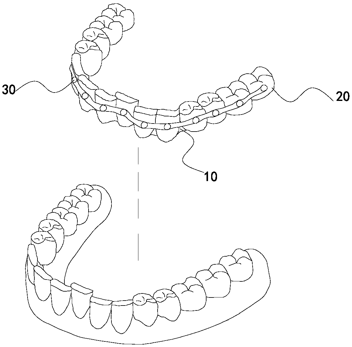
[0043] This embodiment discloses a set for orthodontics, which includes a brace for invisible orthodontics and an accessory mechanism, and the brace for invisible orthodontics includes a brace mechanism, such as figure 1 As described, the braces mechanism of this embodiment includes upper jaw braces and mandibular braces 10. The upper jaw braces are matched with the upper teeth, and the lower jaw braces 10 are matched with the lower teeth. The upper jaw and lower jaw braces 10 are generally made by 3D printing, and the upper jaw braces are made by 3D printing. Both the lower jaw braces 10 and the lower jaw braces 10 are made of transparent materials. The upper jaw braces are provided with multiple crown sleeves 20. The multiple crown sleeves 20 on the upper jaw braces are connected in sequence to form a U-shaped structure. The lower jaw braces 10 are also provided with multiple crowns. The multiple crown sleeves 20 on the mandibular braces 10 are also connected in sequence to form a U-shaped structure. According to the number of human teeth, there are generally 14 crown sleeves 20 on the upper and lower braces 10. The size and shape of the teeth are different, the size and shape of the crown sleeve 20 are also different, such as image 3 As shown, each dental crown sleeve 20 includes an occlusal surface 21 and a dental surface mechanism. The dental surface mechanism includes an outer dental surface 22 and an inner dental surface 23. The outer dental surface 22 and the inner dental surface 23 are connected by the occlusal surface 21. A crown groove is formed between the surface 22, the inner tooth surface 23, and the occlusal surface 21, and the adjacent crown grooves communicate with each other. Such as figure 2 As shown, in order to enable the brace mechanism to be used in conjunction with the accessory mechanism, the crown cover 20 is provided with an accessory avoidance mechanism. The accessory avoidance mechanism in this embodiment is an accessory avoidance groove 30, and the accessory mechanism communicates with the crown cover 20 through the accessory avoidance groove 30 In cooperation, the accessory mechanism provides the upper jaw braces and the mandibular braces 10 with a point of force when correcting teeth, so that the upper and lower braces 10 have corrective force during the correction phase. The adjacent accessory avoidance grooves 30 are provided with correction wire avoidance grooves 40. The correction wire avoidance groove 40 communicates with the accessory avoidance groove 30, wherein the accessory avoidance groove 30 and the correction wire avoidance groove 40 protrude from the inner side of the outer tooth surface to the outer side of the tooth surface, and the accessory avoidance groove 30 matches the accessory mechanism, The correction wire avoidance groove 40 matches the correction wire.
[0044] Such as Figure 4 As shown, the attachment mechanism includes an attachment body 50. After the upper and lower braces are removed, the attachment mechanism still has the corrective force on the teeth, so that the corrected teeth will not fall back to the position before correction, such as Figure 4 As shown, in this embodiment, the accessory body 50 is provided with a through hole penetrating the accessory body 50, and a correction wire groove 60 is formed between the through hole and the accessory body. The correction wire groove 60 matches the correction wire, and the correction wire groove 60 is used for The orthodontic wire passes through to form a corrective force on the teeth; Figure 5 As shown, it is an accessory mechanism of another structure. The accessory mechanism includes an accessory main body 50 and an accessory end cover 70 that cooperates with the accessory main body 50. The accessory main body 50 is provided with a correction wire groove 60 that penetrates the accessory main body 50. An opening is provided above 60, and the opening is communicated with the correcting wire slot 60. The accessory end cover 70 is used to open or close the opening. The accessory end cover 70 can open and close the opening in any way, which is not limited in this embodiment; The attachment mechanism of the embodiment can also be designed as Image 6 As shown, Image 6 The shown accessory mechanism includes an accessory main body 50. The bottom of the accessory main body 50 is provided with a groove recessed toward the top of the accessory main body. When the accessory main body 50 is bonded to the tooth, an orthodontic wire groove 60 is formed between the groove and the tooth. The wire groove 60 penetrates through the accessory main body 50.
[0045] The structure of the accessory mechanism of this embodiment is not limited to the above three structures, and the shape of the accessory mechanism can be regular, such as hemispherical and semi-elliptical, or irregular, and the accessory mechanism can be metal or ceramic. It can also be a polymer resin, and the bottom of the accessory mechanism of this embodiment has an accessory bottom surface, the maximum vertical distance between the upper side of the accessory bottom surface and the lower side of the accessory bottom surface is the first dimension, and the first dimension is the accessory mechanism 20% to 70% of the vertical axis of the crown of the bonded tooth, the maximum horizontal distance between the left side of the bottom surface of the attachment body and the right side of the attachment body is the second dimension, and the second dimension is the tooth bonded by the attachment mechanism 20% to 50% of the horizontal axis of the crown, such as Picture 11 As shown, due to the different sizes of the crowns of the teeth, the shapes and sizes of the attachment mechanisms on the upper and lower teeth, from the incisor position to the left and right sides, are also different. Such as image 3 As shown, the attachment mechanism of this embodiment is also provided with an attachment hole 54. The number of attachment holes 54 may be one or more. The attachment holes 54 may be set to communicate with and cross the correction wire groove 60; 54 can be set to communicate with the correcting wire groove 60 and perpendicular to the correcting wire slot 60; the attached hole 54 can also be set to be parallel to the correcting wire slot 60; the attached hole 54 can also be set to have a different surface structure with the correcting wire slot 60. In actual use, the attachment holes 54 of different structures can be selected according to needs. In use, orthodontic wires or other components can be provided on the attachment holes 54 for correcting teeth. In order to facilitate the wearing of the braces, the attachment mechanism can smoothly enter the attachment avoiding mechanism, such as Figure 7 , Figure 8 As shown, any side of the accessory mechanism is set as a smooth first inclined surface 51. When the brace mechanism is installed, the accessory escape groove 30 on the dental armature mechanism slides down along the first inclined surface 51; or any side of the accessory escape groove 30 One side is set as a smooth second side, and the accessory avoiding mechanism slides into the accessory avoiding groove 30 along the second inclined surface; or a first inclined surface 51 is arranged on any side of the accessory mechanism, and a second inclined surface 51 is arranged at the corresponding position of the accessory avoiding groove. The inclined surface, and the inclination angles of the first inclined surface and the second inclined surface are the same, which makes it easier for the accessory mechanism to enter the accessory avoiding mechanism.
[0046] In order to bond the attachment mechanism to the tooth, such as Figure 4 , Figure 5 or Image 6 As shown, the bottom surface of the accessory mechanism of this embodiment is provided with a bonding surface 80. The bonding surface 80 and the accessory mechanism may be an integral structure or a split structure. The bonding surface 80 is used after the adhesive is applied. To bond to the teeth, in order to increase the adhesion between the bonding surface 80 and the teeth, and to prevent the attachment mechanism from falling off the teeth, the bonding surface 70 may be provided with uneven patterns.
[0047] In order to fix the accessory mechanism and the accessory escape groove 30, in the present embodiment, a slot 24 is provided on the accessory mechanism, and at the same time, a buckle 52 matching the slot 24 is provided at the corresponding position of the crown sleeve, and the accessory mechanism passes The slot 24 and the buckle 52 are fixed on the crown sleeve 20. In order to facilitate the installation of braces, such as image 3 As shown, a bend 53 may also be provided on the end of the outer tooth surface 22 of the invisible brace near the root of the tooth, and the bend 53 extends along the outer tooth surface 22 outside the outer tooth surface 22.
[0048] When the orthodontic suit is in use, the number of crown sleeves can be set according to the needs of orthodontics. During the orthodontic process, an accessory mechanism can be installed on each tooth; it can also be installed on only some teeth; It is also possible to install multiple attachment mechanisms on the same tooth, and there can be multiple teeth spaced between the two attachment mechanisms installed on the teeth, so that the orthodontic wire can provide greater correction strength for the orthodontic tooth, and the orthodontic wire can be based on the expectations of the teeth. The corrective effect of wearing, such as figure 2 As shown, orthodontic wires can be worn on all teeth; Picture 10 As shown, it is also possible to provide the orthodontic wire avoidance grooves on only part of the teeth, and only partially wear the orthodontic wire. The orthodontic wire of this embodiment can be square or circular.
[0049] In the orthodontic stage, generally choose to wear orthodontic wires under the following conditions: 1. The amount of movement of the teeth is relatively large; 2. The amount of movement of the teeth is not large, but a great support is required during the correction process; 3. One of them When the group of teeth does not need to move, fix the teeth with the orthodontic wire; 4. After wearing the upper jaw braces or the mandibular braces, there is a deviation of 1mm to 5mm between the corrective effect of the teeth and the expected corrective effect; 5. When the torsion of the teeth reaches 10 degrees Above, the opening and closing of the teeth is more than 1mm, and the extension or decline of the teeth is more than 1mm.
[0050] The accessory mechanism of this embodiment can be manufactured by powder metallurgy manufacturing, 3D printing, or processing and manufacturing using light-curing resin. When the light-curing resin is processed, the resin is filled into the accessory recesses of the upper or lower braces, and the light-cured Light irradiation makes the resin solidify, and the solidified resin can be taken out.
[0051] The method of using the orthodontic suit of this embodiment includes the following steps:
[0052] First, use 3D printing technology to print the upper jaw braces and mandibular braces to match the expected corrective effects of the upper and lower teeth, and the mandibular braces to match the expected corrective effects of the lower teeth, and determine the installation position of the accessory mechanism;
[0053] After acid etching the attachment position on the tooth, use an adhesive to bond the attachment mechanism to the tooth;
[0054] Pass the corrective wire through the corrective wire slot 60 and adjust the corrective force of the corrective wire at the same time;
[0055] The upper jaw braces are installed on the upper teeth, the lower jaw braces are installed on the lower teeth, so that the accessory mechanism enters the accessory escape groove 30, and the correction wire enters the correction wire escape groove 60.
[0056] The orthodontic set of this embodiment can realize the switch from non-invisible correction to invisible correction, and the switching method includes the following steps:
[0057] First, use 3D printing technology to print the upper and lower braces, and determine the installation position of the accessory mechanism;
[0058] After acid etching is performed at the attachment position on the tooth, the attachment mechanism is bonded to the tooth with an adhesive;
[0059] Pass the corrective wire through the corrective wire slot 60 and adjust the corrective force of the corrective wire at the same time;
[0060] In order to accurately express the effect of orthodontics and improve the speed of orthodontics, the upper jaw braces are installed on the upper teeth and the lower jaw braces are installed on the lower teeth, so that the accessory mechanism enters the accessory avoidance groove 30, and the orthodontic wire enters the orthodontic wire escape groove 60.
[0061] The orthodontic set of this embodiment can also realize the switch from invisible correction to non-invisible correction. The switching method includes the following steps:
[0062] First, use 3D printing technology to print the upper and lower braces, and determine the installation position of the accessory mechanism;
[0063] After acid etching is performed on the attachment position of the tooth, the attachment mechanism is bonded to the tooth with an adhesive;
[0064] Pass the corrective wire through the corrective wire slot 60 and adjust the corrective force of the corrective wire at the same time;
[0065] Install the upper jaw braces on the upper teeth and the lower jaw braces on the lower teeth, so that the accessory mechanism enters the accessory escape groove 30, and the correction wire enters the correction wire escape groove 60;
[0066] In order to avoid frequent removal and installation of upper and lower braces, the upper jaw braces are removed from the upper teeth and the lower jaw braces are removed from the lower teeth without affecting the correction effect.
[0067] The advantages or working principles of this embodiment are as follows:
[0068] 1. The braces mechanism and the attachment mechanism work together to correct the teeth. During the orthodontics, the correction wire can be passed through the correction wire groove 60, so that the braces mechanism and the attachment mechanism can apply the corrective force to the teeth together, so that the correction data can be expressed more accurately. The effect is better. At the same time, when the brace mechanism is removed, the attachment mechanism still exerts a force on the teeth, so that the orthodontic tooth will not fall back to the position before the correction due to the removal of the brace mechanism, and the correction effect cannot be achieved.
[0069] 2. In the orthodontic stage, by adjusting the correction wire to control the strength of the teeth and the direction of the movement of the teeth, there is no need to frequently replace the braces and accessories, which saves the doctor's operation time during the correction process, and saves the braces and accessories At the same time, it reduces the damage to the teeth caused by acid erosion when the attachment mechanism is installed.
[0070] 3. The orthodontic wire escape groove 40 on the brace mechanism. After the brace mechanism is installed, the orthodontic wire can enter the orthodontic wire escape groove 40 to facilitate the coordination of the accessory mechanism and the brace mechanism after the orthodontic wire is installed. At the same time, the accessory mechanism and the brace mechanism Both have corrective power on teeth.
[0071] 4. The correction wire avoiding groove 40 communicates with the accessory avoiding groove 30. After the accessory mechanism enters the accessory avoiding groove 30, the correction wire can also enter the correction wire avoiding groove 40 smoothly.
[0072] 5. After wearing the brace mechanism, the teeth are located in the crown groove. For the teeth that need to be extracted, the height of the crown groove is higher than the height of the crown, which is beneficial to the correction of the teeth.
[0073] 6. After the accessory end cover 70 is opened, the correction wire enters the correction wire slot 60 through the opening. After the accessory end cover 70 is closed, the correction wire is fixed in the correction wire slot 60 so that the correction wire will not pass from the correction wire slot during the correction process. It slides out within 60, it is easy to install and remove the correction wire and convenient to operate.
[0074] 7. An orthodontic wire groove 60 is formed between the groove and the tooth. The groove and the accessory main body 50 are an integral structure, which has a simple structure and can achieve a better correction effect.
[0075] 8. There are patterns on the bonding surface 80. The patterns increase the friction between the attachment mechanism and the teeth, so that the bonded attachment mechanism will not easily fall off the teeth during the correction process.
[0076] 9. The attached hole 54 is used to pass the orthodontic wire or other components during the correction process, and cooperate with the braces mechanism or the orthodontic wire to correct the teeth, so that the correction effect is better.
[0077] 10. The size of the attachment mechanism is limited, so that the attachment mechanism and the brace mechanism have the best effect on teeth correction, and at the same time, minimize the damage of the attachment mechanism to the tooth surface.
[0078] 11. The first inclined plane 51 and the second inclined plane facilitate the attachment mechanism to enter the attachment avoidance mechanism, and facilitate the wearing of upper jaw braces and mandibular braces, so that the orthodontist can easily re-wear the upper jaw braces and mandibular braces after removing the upper and lower braces by themselves Braces, at the same time, save wearing time.
[0079] 12. The attachment mechanism is fixed on the crown sleeve through the card slot 52 and the buckle 24, so that the attachment mechanism will not slip out of the attachment avoiding mechanism during the correction process and fail to achieve the ideal correction effect.
[0080] 13. The upturn 53 on the outer tooth surface facilitates the adjustment of the upper and lower braces during installation. Through adjustment, all attachment mechanisms can enter the attachment avoidance mechanism.
[0081] 14. The orthodontic suit can switch between invisible correction and non-invisible correction at will. After the invisible correction is switched to non-invisible correction, the attachment mechanism still has the corrective power on the teeth, and the teeth will not fall back to the position before the correction and lose the correcting effect , After the non-invisible correction is switched to the invisible correction, the correction data of the teeth during the correction process can be expressed more accurately. At the same time, the teeth look more beautiful during the correction process. The orthodontic set is helpful for the corrector during the correction process. Any switch and selection of invisible correction and non-invisible correction.
Example
[0082] The second embodiment:
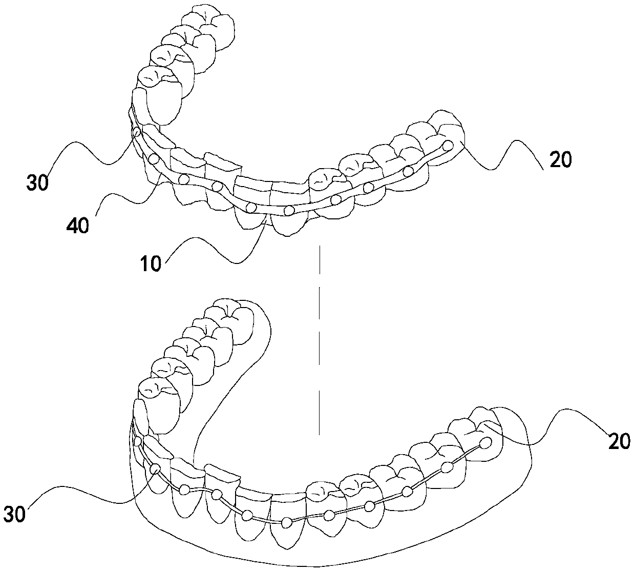
[0083] This embodiment discloses a brace for orthodontics, which includes an accessory mechanism and a brace for invisible orthodontics. The brace for invisible orthodontics includes a brace mechanism. The accessory mechanism of this embodiment has the same structure as that of the first embodiment. The structure of the braces mechanism of the embodiment is different from that of the first embodiment. The braces mechanism of this embodiment includes upper jaw braces and mandibular braces 10. The upper jaw braces are matched with the maxillary teeth, the lower jaw braces 10 are matched with the lower teeth, and the upper jaw braces and the lower jaw braces are matched. 10 is generally made by 3D printing, and the upper jaw braces and the lower jaw braces 10 are made of transparent materials. There are multiple crown covers 20 on the upper braces, and the multiple crown covers 20 on the maxillary braces are connected in sequence to form a U-shaped structure. The mandibular braces 10 are also provided with multiple crown sleeves 20, and the multiple crown sleeves 20 on the mandibular braces 10 are also connected in sequence to form a U-shaped mechanism. Each crown sleeve 20 includes an occlusal surface 21 and a dental surface mechanism. The tooth surface mechanism includes an outer tooth surface 22 and an inner tooth surface 23. The outer tooth surface 22 and the inner tooth surface 23 are connected by an occlusal surface 21. A crown groove is formed between the outer tooth surface 22, the inner tooth surface 23 and the occlusal surface 21. The adjacent tooth crown grooves communicate with each other inside. Such as Picture 12 As shown, the dental crown sleeve is provided with an accessory avoiding mechanism. The accessory avoiding mechanism in this embodiment is an accessory avoiding hole 90. The accessory avoiding hole 90 matches the accessory avoiding mechanism, and the accessory mechanism matches the dental crown through the accessory avoiding hole 90 , The accessory avoiding hole is located on the external tooth surface 22, and the accessory avoiding hole 90 penetrates the external tooth surface 22 front and back. When the upper and lower braces 10 are inserted into the upper and lower teeth, the accessory avoiding mechanism passes through the accessory avoiding hole 90 to kyphosis From the outer tooth surface of the upper or lower braces 10. In order to facilitate the insertion of the crown cover 20 into the tooth with the attachment mechanism, a bend 53 can be provided on the outer tooth surface of the crown cover near the end of the tooth root, and the bend 53 is along the outer tooth surface to the outside of the outer tooth surface extend.
[0084] The method of using the orthodontic suit of this embodiment includes the following steps:
[0085] First, use 3D printing technology to print the upper and lower braces, and determine the installation position of the accessory mechanism;
[0086] After acid etching the attachment mechanism installation position on the tooth, use an adhesive to bond the attachment mechanism to the tooth;
[0087] Install the upper jaw braces on the upper teeth, and install the lower jaw braces on the lower teeth so that the accessory mechanism enters the accessory escape hole.
[0088] When the orthodontic set of this embodiment is used, the attachment mechanism can be installed on each tooth, or the attachment mechanism can be installed only on some teeth, or multiple attachment mechanisms can be installed on the same tooth. For example, during use, the upper jaw braces and the lower jaw braces 10 may not be installed, and the correcting wire can be directly installed on the attachment mechanism to achieve the purpose of correction.
[0089] Compared with the first embodiment, the advantage of this embodiment is: the accessory escape hole 90 of this embodiment allows the accessory mechanism to pass through, and the accessory mechanism provides a point of force for the brace mechanism, so that the brace mechanism can drive the teeth to any direction during the correction process. Moving in the direction, a better correction effect can be achieved without correction wire.
PUM


Description & Claims & Application Information
We can also present the details of the Description, Claims and Application information to help users get a comprehensive understanding of the technical details of the patent, such as background art, summary of invention, brief description of drawings, description of embodiments, and other original content. On the other hand, users can also determine the specific scope of protection of the technology through the list of claims; as well as understand the changes in the life cycle of the technology with the presentation of the patent timeline. Login to view more.
Similar technology patents
Image correction method and device, electronic equipment and storage medium
Owner:BEIJING CENTURY TAL EDUCATION TECH CO LTD
Method for improving precision of carbonatite dynamic and static Young modulus conversion model
ActiveCN111666665AGood correction effectGuarantee feasibility and convenience
Owner:CHINA UNIV OF PETROLEUM (EAST CHINA)
Method for correcting errors of towed sonar system by utilizing neighbor interference
Owner:CHINA SHIP DEV & DESIGN CENT
Mini track for opening hand skin of children with syndactylia
Owner:NANJING CHILDRENS HOSPITAL
Classification and recommendation of technical efficacy words
- accurate expression
- good correction effect
New event theme extraction method
Owner:QINGDAO UNIV
Projection image correction method and device
PendingCN109873997AGood correction effectgood visual experience
Owner:GUIAN NEW DISTRICT XINTE ELECTRIC VEHICLE IND CO LTD
Modified structure of welding pipe squeezing roller seat
ActiveCN103495669Agood correction effectGuaranteed roundness
Owner:ZHEJIANG KINGLAND PIPELINE & TECH CO LTD
Optical lens, camera module and electronic device
ActiveCN110262017AInflection Force Distribution Specificationgood correction effect
Owner:GUANGDONG OPPO MOBILE TELECOMM CORP LTD