Novel power battery combination device

A power battery and combined device technology, applied in the direction of power devices, electric power devices, battery pack components, etc., can solve the problems of grooves that are prone to edge formation, battery jamming, and dust entry, etc., to achieve convenient operation and simple structure Effect

Inactive Publication Date: 2018-10-19
玉环新航工业设计有限公司
View PDF0 Cites 3 Cited by
  • Summary
  • Abstract
  • Description
  • Claims
  • Application Information

AI Technical Summary

Problems solved by technology

[0002] At present, new energy vehicles are widely used, and the batteries in new energy vehicles need to be replaced or disassembled and charged frequently. The batteries in traditional new energy vehicles are directly installed in the grooves of new energy vehicles and need to be lifted manually. Therefore, it is more labo...

Method used


Image

  • Novel power battery combination device
  • Novel power battery combination device
  • Novel power battery combination device

Examples


Embodiment Construction

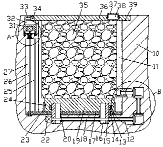
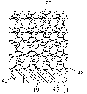
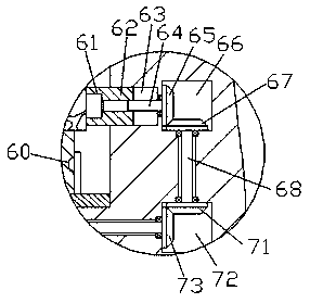
[0016] Combine below Figure 1-4 The present invention will be described in detail.

[0017] refer to Figure 1-4 , according to an embodiment of the present invention, a new type of power battery combination device includes a storage cavity 11 arranged in the top of the new energy vehicle body 10 and a battery body 35 locked and installed in the storage cavity 11. The inner wall on the left side of the chamber 11 is provided with a slide guide chamber 27, and a guide slide rod 25 extending up and down is fixed in the guide slide chamber 27, and a jacking plate 17 is installed slidingly in the guide slide chamber 27, so that The lifting plate 17 protrudes into the receiving chamber 11 and is slidably connected with it. The first screw rod 26 threadedly connected with the lifting plate 17 is provided in the sliding guide chamber 27. The bottom end of the screw 26 is rotatably connected to the inner bottom wall of the sliding guide chamber 27 , the top end of the first screw 2...


PUM


Abstract

The invention discloses a novel power battery combination device which comprises a containing cavity formed in the top of a new energy vehicle body and a battery body locked in the containing cavity.A sliding guide cavity is formed in the inner wall on the left side of the containing cavity. A sliding guide rod extending up and down is fixedly arranged in the sliding guide cavity. A jacking boardis installed in the sliding guide cavity in a sliding fit mode and extends into the containing cavity to be in sliding fit connection with the containing cavity. A first screw in thread fit connection with the jacking board is arranged in the sliding guide cavity. The tail end at the bottom of the first screw is in running fit connection with the inner bottom wall of the sliding guide cavity. Thetail end at the top of the first screw is fixedly connected with a first rotary shaft. A power cavity is formed in the portion, on the upper side of the sliding guide cavity, of the new energy vehicle body. The first rotary shaft is rotationally arranged between the power cavity and the sliding guide cavity. A sliding seat is installed in the power cavity in a sliding fit mode.

Description

technical field [0001] The invention relates to the technical field of power battery assembly, in particular to a novel power battery assembly device. Background technique [0002] At present, new energy vehicles are widely used, and the batteries in new energy vehicles need to be replaced or disassembled and charged frequently. The batteries in traditional new energy vehicles are directly installed in the grooves of new energy vehicles and need to be lifted manually. Therefore, it is more laborious. Moreover, due to the long-term use of new energy vehicles, the grooves are prone to edge formation or particles such as dust, which are easy to jam the battery and further affect the removal of the battery. Moreover, the traditional battery needs to be manually removed from the battery. Plug connection, inconvenient to use. Contents of the invention [0003] The object of the present invention is to provide a novel power battery assembly for overcoming the above-mentioned def...

Claims


Application Information

Patent Timeline
IPC IPC(8): B60K1/04H01M2/10H01M50/249
CPCB60K1/04B60K2001/0405B60K2001/0466H01M2220/20H01M50/256H01M50/20Y02E60/10
Inventor 张波
Owner 玉环新航工业设计有限公司
Why Eureka
Try Eureka