Anti-collision type car charging pile

A technology for car charging and charging piles, which is applied in electric vehicle charging technology, charging stations, electric vehicles, etc., can solve the problems of easy opening of the cover and reducing the anti-collision effect of the display interface.

Inactive Publication Date: 2018-10-19
十堰派生工贸有限公司
View PDF1 Cites 1 Cited by
  • Summary
  • Abstract
  • Description
  • Claims
  • Application Information

AI Technical Summary

Problems solved by technology

However, due to the unpredictability of the impact, for heavier impacts, it is far from enough to protect the pillar by applying pressure to the third and fourth fixing plates by clamping bolts. In addition, no fixing measures are taken after the cover is closed , the sliding cover is easy to open by itself, reducing the anti-collision effect of the display interface

Method used


Image

  • Anti-collision type car charging pile
  • Anti-collision type car charging pile
  • Anti-collision type car charging pile

Examples


Embodiment 1

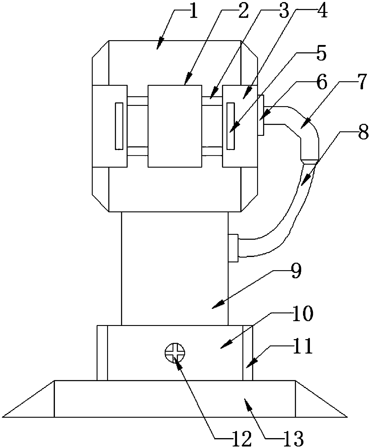
[0025] see Figure 1-4 , this embodiment provides an anti-collision vehicle charging pile, including a charging pile main body 1; a display interface 2 is provided on the outer surface of the charging pile main body 1, and sliding rails 3 are arranged on the left and right sides of the display interface 2 The left and right sides of the sliding track 3 are provided with a cover body 4, and the outer surface of the cover body 4 is fixed with a handle 5, two cover bodies 4 are provided, and the cover body 4 is symmetrically distributed on the outside of the display interface 2, The sum of the lengths of the cover 4 is greater than the length of the display interface 2, and the sum of the widths of the cover 4 is greater than the width of the display interface 2, ensuring that the cover 4 can completely cover the display interface 2, and the gap between the cover 4 and the sliding track 3 It is a sliding connection structure; the connection between the handle 5 and the cover 4 is...

Embodiment 2

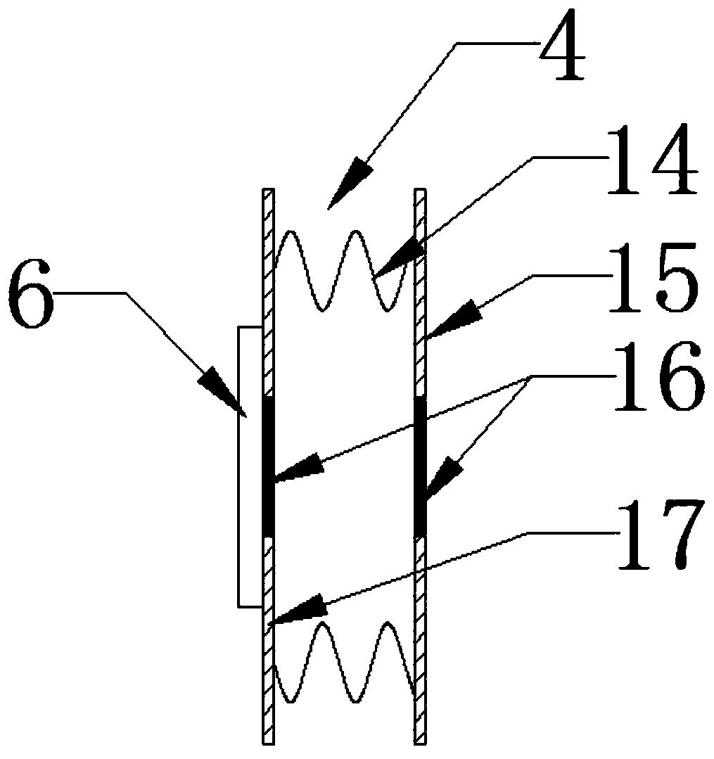
[0029] see image 3 , in this embodiment, the cover plate 17 and the middle part of the side of the rubber plate 15 are provided with a magnet 16, through the magnet 16, the two covers 4 can attract each other when sliding and closing, thereby fixing the two covers 4.

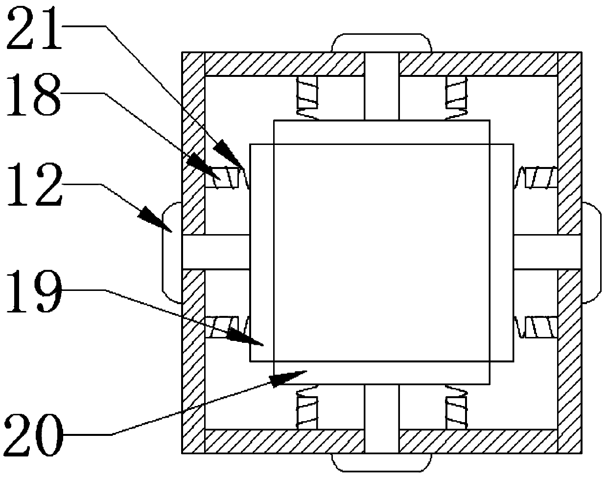
[0030]The working principle of the present invention is: by tightening the fastening bolt 12, the third fixed plate 19 and the fourth fixed plate 20 are clamped and fixed to the connecting strut 9, and the fixed connecting strut 9 is protected against collision; at the same time, the second spring 21 is used to It is supported between the first fixed plate 10 and the third fixed plate 19 to further counteract the impact force. In addition, when the fixed connection pillar 9 is subjected to a huge impact, in order to prevent the failure of both the third fixed plate 19 and the second spring 21, it is located at The protective rod 18 inside the second spring 21 can play a final protective role; the display interf...


PUM


Abstract

The invention provides an anti-collision type car charging pile and belongs to the technical field of charging piles. The anti-collision type car charging pile comprises iron blocks located at the left end and rubber blocks on the right sides of the iron blocks. The iron blocks are welded to first fixing plates, and the right sides of the rubber blocks and third fixing plates are appropriately spaced. Protective rods are sleeved with second springs, compressed springs serves as the second springs, one ends of the second springs are fixed to the first fixing plates, and the other ends of the second springs are fixed to the third fixing plates. By screwing fastening bolts, the third fixing plates and fourth fixing plates clamp a fixed connection supporting column, and thus the fixed connection supporting column is subjected to anti-collision protection; meanwhile, the second springs are supported between the first fixing plates and the third fixing plates, thus the collision intensity isfurther counteracted, in addition, when the fixed connection supporting column suffers from large collision, in order to prevent the third fixing plates and the second springs from losing efficacy, the protective rods located inside the second springs can achieve the final protection effect; and through magnets, two cover bodies can attract mutually when slidably closed, and accordingly the two cover bodies are fixed.

Description

technical field [0001] The invention relates to a charging pile, in particular to an anti-collision type automobile charging pile. Background technique [0002] The function of the charging pile is similar to the fuel dispenser in the gas station. It can be fixed on the ground or wall, and installed in the parking lot or charging station of public buildings and residential areas. It can charge various types of electric vehicles according to different voltage levels. The charging pile The input end of the battery is directly connected to the AC power grid, and the output end is equipped with a charging plug for charging the electric vehicle. However, there are a series of defects in the common car charging piles on the market. For example, the car charging pile only adds an anti-collision structure inside, and it cannot easily prevent the display interface from colliding, so that the display interface will be easy when a collision occurs. If it is damaged, the base and the p...

Claims


Application Information

Patent Timeline
Patent Type & Authority Applications(China)
IPC IPC(8): B60L11/18
CPCB60L53/31Y02T10/70Y02T10/7072Y02T90/12
Inventor 李成彦雷涛李先锋
Owner 十堰派生工贸有限公司
Why Eureka
Try Eureka