
Quenching device

A technology of quenching device and quencher, which is applied in the direction of quenching device, furnace type, furnace, etc., can solve the problems of low work efficiency and unstable treatment effect, and achieve the effect of simple structure, changing the effect of heat treatment, and easy realization

Inactive Publication Date: 2018-10-19
张家港市后塍热处理厂
View PDF0 Cites 1 Cited by
  • Summary
  • Abstract
  • Description
  • Claims
  • Application Information

AI Technical Summary

Problems solved by technology

In order to ensure product quality, small areas need to be heat treated one by one, not only the work efficiency is low, but also the treatment effect is unstable

Method used


Image

  • Quenching device
  • Quenching device

Examples


Embodiment

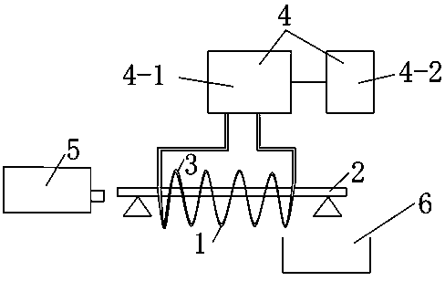
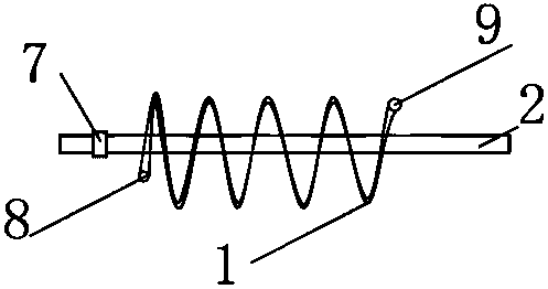
[0017] Embodiment, a kind of quenching device, see figure 1 , including a helical coil quencher 1 surrounded by a hollow copper tube 3, one end of the helical coil quencher 1 is a feed end 8, and the other end is a discharge end 9, and the helical coil quencher 1 is provided with The track 2 for the workpiece to pass through, the hollow copper tube 3 is provided with a resistance wire and the two ends are connected with the heater 4 . The feeding end 8 is provided with an oil cylinder 5, and the push rod of the oil cylinder 5 can expand and contract in the horizontal direction.

[0018] The heater 4 includes a connected intermediate frequency outdoor heater 4-1 and an indoor heater 4-2. Track 2 is two parallel steel pipes, see figure 2 .

[0019] A pool 6 is provided below the discharge end of the helical coil quencher 1 .

[0020] The tray 7 is provided with a side wall and one side facing the discharge end 8 is open, and the push rod of the oil cylinder 5 is connected w...


PUM


Abstract

The invention provides a quenching device. The quenching device includes a spiral coil quencher which is surrounded by a hollow copper pipe, wherein one end of the spiral coil quencher is a feeding end and the other end is a discharge end. A rail for workpiece running is arranged in the spiral coil quencher. A resistance wire is arranged in the hollow copper pipe, wherein two ends of the hollow copper pipe are connected with a heater. The spiral coil quencher is formed by the hollow copper pipe in a surrounded mode, a workpiece traveling in the spiral coil quencher is subjected to quenching treatment through the hollow copper pipe, the continuous quenching treatment of small parts can be realized, the effect of heat treatment to the processing workpiece can be changed, the adjustment of the heat treatment can be more precisely controlled, and not only is the work efficiency improved, but also the stability of the effect of the heat treatment is improved.

Description

technical field [0001] The invention relates to the field of metal surface treatment, in particular to a quenching device. Background technique [0002] Heat treatment is an important basic technology in the machinery industry. Through heat treatment, the internal structure of steel can be changed, thereby improving the performance of steel. Proper heat treatment can significantly improve the mechanical properties of steel and prolong the service life of machine parts. Proper heat treatment can eliminate various defects caused by casting, forging, welding and other thermal processing processes, refine grains, eliminate segregation, reduce internal stress, and make the structure and properties of steel more uniform. Due to the various shapes and structures of mechanical parts, different devices are required for heat treatment for different parts. In order to ensure product quality, small areas need to be heat treated one by one, which not only has low work efficiency, but a...

Claims


Application Information

Patent Timeline
Patent Type & Authority Applications(China)
IPC IPC(8): C21D1/42C21D1/63C21D9/00
CPCC21D1/42C21D1/63C21D9/0062C21D9/0068Y02P10/25
Inventor 陆辉
Owner 张家港市后塍热处理厂
Learn More