Ultra-high performance concrete and partial steel beam composite cap beam and construction method thereof

An ultra-high-performance, concrete technology, applied in bridges, bridge parts, bridge materials, etc., can solve the problems of difficult overall prefabricated hoisting, high cost of steel structure cover beams, etc., achieve good economy, save steel consumption, and reduce on-site operations volume effect

Pending Publication Date: 2018-10-19
HUNAN UNIV
View PDF1 Cites 9 Cited by
  • Summary
  • Abstract
  • Description
  • Claims
  • Application Information

AI Technical Summary

Problems solved by technology

[0006] Therefore, in order to make full use of the advantages of the excellent tensile properties of steel and the high compressive strength and high toughness of ultra-high performance concrete, and solve the problem that the conventional large cantilever prestressed concret

Method used


Image

  • Ultra-high performance concrete and partial steel beam composite cap beam and construction method thereof
  • Ultra-high performance concrete and partial steel beam composite cap beam and construction method thereof
  • Ultra-high performance concrete and partial steel beam composite cap beam and construction method thereof

Examples


Embodiment 1

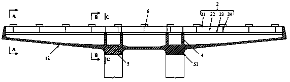
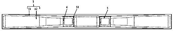
[0053] Such as Figure 1 to Figure 6 As shown, an ultra-high-performance concrete-partial steel beam composite cover beam includes a hollow trough-shaped body 1 and a roof steel beam 2 cast by ultra-high-performance concrete, and the roof steel beam 2 is laid on the hollow trough-shaped body 1, The height of the roof steel beam 2 is ≥ 1 / 10 of the total height of the combined cover beam, wherein the total height of the combined cover beam is the sum of the height of the roof steel beam and the height of the hollow groove body, so that the neutral axis of the combined cover beam is close to The roof steel beam 2 (that is, the neutral axis is located in the hollow trough body 1 ) or is located in the roof steel beam 2 .

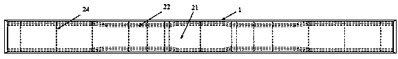
[0054] The hollow trough body 1 includes a cover beam web 11 and a cover beam bottom plate 12, and the roof steel beam 2 includes a steel beam upper flange plate 21, a steel beam web plate 22, a steel beam lower flange plate 23 and a steel beam diaphragm plate ...

Embodiment 2

[0072] Such as Figure 7 to Figure 12 As shown, an ultra-high-performance concrete-partial steel beam composite cover beam of this embodiment includes a hollow trough-shaped body 1 cast by ultra-high-performance concrete and a roof steel beam 2, and the roof steel beam 2 is laid on the hollow trough-shaped Above the body 1, the height of the roof steel beam 2 is ≥ 1 / 10 of the total height of the combined cover beam, wherein the total height of the combined cover beam is the sum of the height of the roof steel beam and the height of the hollow groove body, so that the combined cover beam The neutral axis is close to the roof steel beam (that is, the neutral axis is located in the hollow trough body) or is located in the roof steel beam.

[0073] The hollow trough body 1 includes a cover beam web 11 and a cover beam bottom plate 12, and the roof steel beam 2 includes a steel beam upper flange plate 21, a steel beam web 22 and a steel beam lower flange plate 23, and the roof stee...


PUM

PropertyMeasurementUnit
Heightaaaaaaaaaa
Thicknessaaaaaaaaaa
Heightaaaaaaaaaa

Abstract

The invention discloses an ultra-high performance concrete and partial steel beam composite cap beam and a construction method thereof. The composite cap beam comprises a hollow groove-shaped body cast by ultra-high performance concrete and a roof steel beam, wherein the roof steel beam is laid on the hollow groove-shaped body; the height of the roof steel beam is >= 1/10 of the total height of the composite cap beam; and a neutral axis of the composite cap beam is positioned near the roof steel beam or inside the roof steel beam. The roof steel beam and the ultra-high performance concrete hollow groove-shaped body of the composite cap beam are integrally formed at one time and are integrally prefabricated in a factory so as to enable the composite cap beam to have better integrity, reduceprocedures performed in a construction site, ensure the manufacturing quality of components, save the amount of steel and achieve good economical efficiency. The construction method of the compositecap beam does not need additional investment of new equipment or new skill training for construction workers. The construction method is simple and quick.

Description

technical field [0001] The invention relates to the technical field of a bridge component and its construction, in particular to an ultra-high performance concrete-partial steel beam composite cover beam and a construction method thereof. Background technique [0002] With the acceleration of China's urbanization process, the rapid transformation of roads in major cities in China is in the ascendant, but there are also some problems, among which the shortage of land use and traffic congestion are prominent problems. Therefore, as a solution that can make full use of urban space, urban viaducts are widely used in the rapid transformation of urban roads. In urban viaducts, the use of large cantilever cap beams can make full use of the space under the bridge, which has little impact on the traffic under the bridge, ensures sufficient driving height and vision under the bridge, and occupies less road area. [0003] At present, the commonly used large cantilever cap beams mainly...

Claims


Application Information

Patent Timeline
IPC IPC(8): E01D19/00
CPCE01D19/00E01D2101/268
Inventor 邵旭东邱明红李立峰
Owner HUNAN UNIV
Why Eureka
Try Eureka