
Anti-floating anchor rod and construction methods thereof

An anti-floating anchor and construction method technology, which is applied in infrastructure engineering, sheet pile walls, protection devices, etc., can solve the problems of small friction between the anchor pile and the foundation wall, slurry leakage, and large shrinkage of cement slurry, etc. To achieve the effect of strong anti-floating ability, large friction force and simple operation

Pending Publication Date: 2018-10-19
黄水森 +1
View PDF0 Cites 6 Cited by
  • Summary
  • Abstract
  • Description
  • Claims
  • Application Information

AI Technical Summary

Problems solved by technology

However, the anti-floating ability of existing anti-floating anchor rods is generally not strong
The main reason is: in the process of use, in order to prevent the grouting pipe from clogging, the traditional anti-floating anchor generally uses cement slurry for grouting, that is, the anchor pile of the existing anti-floating anchor is a cement pile, and the shrinkage of the cement slurry If the amount is large, it is easy to cause grouting during the second grouting, and it is easy to cause a gap between the formed anchor pile and the anchor hole, resulting in a small friction between the anchor pile and the anchor hole. At the same time, the groundwater is easy to squeeze into the gap to further reduce the friction between the anchor pile and the foundation wall; the surface of the anchor pile formed after the cement slurry solidifies is relatively smooth, so that the friction between the anchor pile and the foundation wall is small, and the anchoring effect is poor

Method used


Image

  • Anti-floating anchor rod and construction methods thereof

Examples


Embodiment Construction

[0031] In order to further explain the technical solution of the present invention, the present invention will be described in detail below through specific examples.

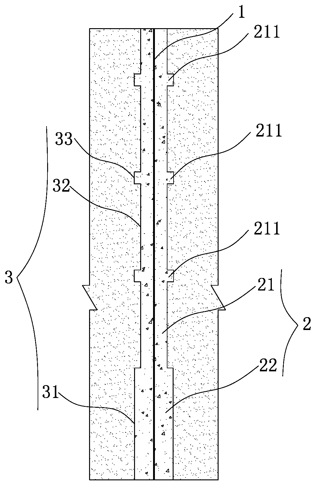
[0032] Such as figure 1 As shown, the present invention discloses an anti-floating anchor, which includes an anchor 1 and an anchor pile 2 that wraps the anchor, and the anchor pile 2 is a concrete pile with a strength of at least C25, so The anchor pile 2 includes a pile main body 21 and an enlarged head 22 connected to the bottom of the pile main body 21; Wherein the height of the expanding head 22 is preferably 2 meters, the diameter of the expanding head 22 is preferably 400 millimeters, the diameter of the pile main body 21 is preferably 250 millimeters, and the anchor rod 1 and the anchor rod pile 2 can be coaxial It is provided that the anchor rod 1 may be threaded steel.

[0033] The anchor pile 2 of a kind of anti-floating anchor rod of the present invention adopts concrete pile, and concrete pile co...


PUM

PropertyMeasurementUnit
Heightaaaaaaaaaa
Diameteraaaaaaaaaa
Diameteraaaaaaaaaa

Abstract

The invention discloses an anti-floating anchor rod. The anti-floating anchor rod comprises an anchor rod body and an anchor rod pile coating the anchor rod body; the anchor rod pile is a concrete pile with the strength being at least C25 and comprises a main pile body and an expanding head connected at the bottom of the main pile body; the expanding head and the main pile body are arranged coaxially and are integrally molded; and the diameter of the expanding head is larger than that of the main pile body. The anchor rod pile of the anchor rod is the concrete pile and comprises the main pilebody and the expanding head connected at the bottom of the main pile body, and the diameter of the expanding head is larger than that of the main pile body, so that the anti-floating anchor rod is high in anti-floating ability. The invention further discloses two construction methods of the anti-floating anchor rod. The two construction methods have the advantages that the methods are simple to operate and the friction force between the molded anchor rod pile and an anchor hole is large.

Description

technical field [0001] The invention relates to the field of engineering construction, in particular to an anti-floating anchor rod and a construction method thereof. Background technique [0002] Due to the insufficient comprehensive load caused by the building's own weight and other external factors, especially for deep foundation pit foundations, in order to balance the buoyancy generated by groundwater, a vertical external force must be applied to the foundation floor to balance the buoyancy. Anti-floating anchor refers to the general term for various pile types that resist the upward displacement of buildings. Existing anti-floating anchors generally include anchors and piles that wrap the anchors. The piles are generally cylindrical. Constrain the trend of the market and play a role in resisting the rise of the foundation. But the anti-floating ability of existing anti-floating anchor rods is generally not strong. The main reason is: in the process of use, in order ...

Claims


Application Information

Patent Timeline
IPC IPC(8): E02D31/12E02D5/80
CPCE02D5/801E02D31/12
Inventor 黄水森黄灿
Owner 黄水森
Learn More