
Monitoring method of cubic scouring safety monitoring device for bridge foundation

A technology for bridge foundation and safety monitoring, which is applied in the test of foundation structure, foundation structure engineering, construction, etc. It can solve the problems such as the influence of the complexity of echo sounding scour addition accuracy, installation error, and large influence of noise

Active Publication Date: 2018-10-19
ZHEJIANG UNIV OF TECH
View PDF3 Cites 7 Cited by
  • Summary
  • Abstract
  • Description
  • Claims
  • Application Information

AI Technical Summary

Problems solved by technology

The disadvantage of ground penetrating radar scour monitoring technology is that it is greatly affected by the noise formed by multiple radiations from the foundation and the riverbed surface, and the scour monitoring effect on the riverbed surface in waters with a water depth greater than 10m is not good.
In particular, the inability to penetrate conductive materials makes it not only impossible to complete the scour monitoring of cohesive soil riverbeds and waters with high salinity, but also difficult to monitor the return silt that has similar electrical characteristics to the bed surface sediment.
The disadvantage of echosounding scour monitoring technology is that whether it is fixed or mobile, the accuracy of echosounding scour addition is easily affected by water depth, water temperature and salinity, sediment concentration and the complexity of underwater terrain, and mobile The echo sounding scour monitoring method is also easily affected by multiple factors such as installation errors, ship attitude measurement errors, and time delay errors.

Method used


Image

  • Monitoring method of cubic scouring safety monitoring device for bridge foundation
  • Monitoring method of cubic scouring safety monitoring device for bridge foundation
  • Monitoring method of cubic scouring safety monitoring device for bridge foundation

Examples


Embodiment Construction

[0112] The present invention will be further described below in conjunction with the accompanying drawings of the description.

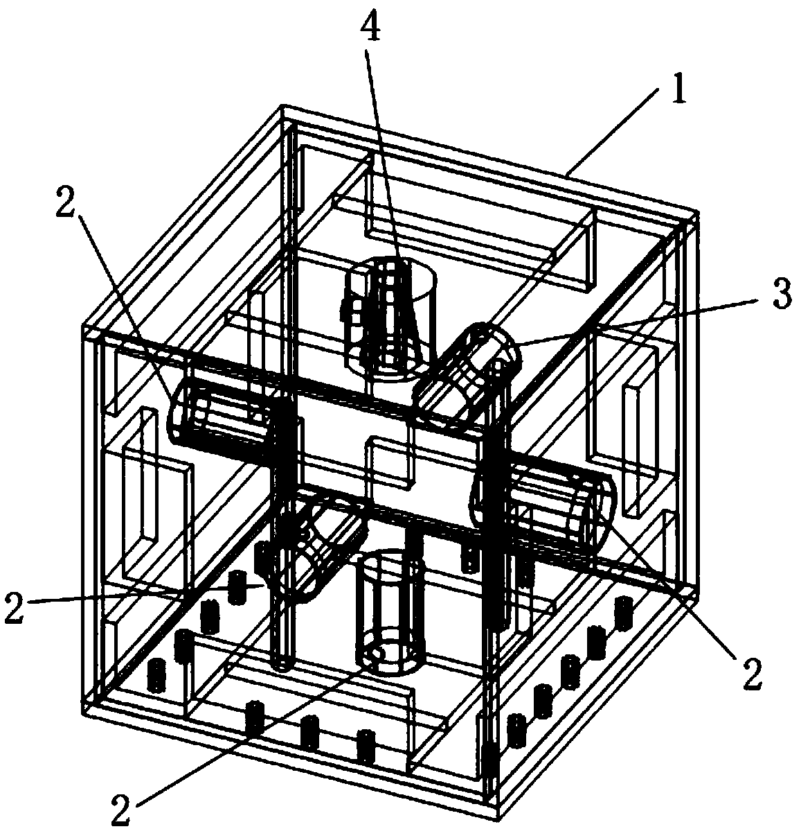
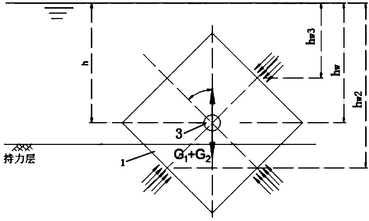
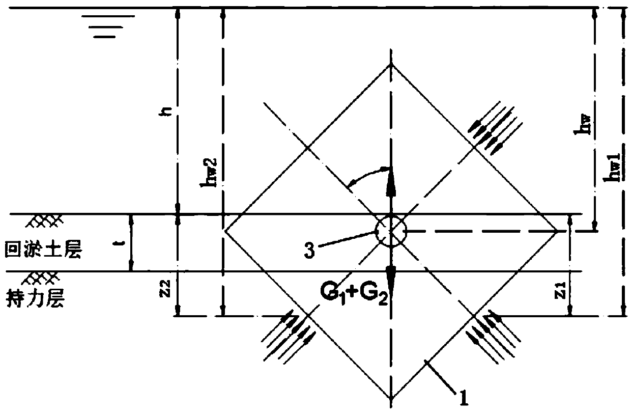
[0113] Such as Figure 1-3 As shown, a cubic bridge foundation scour safety monitoring device includes a caisson 1, a fiber grating pressure sensor 2, a fiber grating seepage pressure sensor 3 and a fiber grating temperature sensor 4.

[0114]Caisson 1, a cubic steel box with a side length of 30cm to 50cm, is composed of 6 steel plates, the wall thickness of the top plate is 15mm to 20mm, and the thickness of the other plates is 10mm to 15mm. The top plate and side plates are connected by welding, considering the complex underwater In the stressed environment, angle steel is welded on the two steel plates connected inside the caisson 1, and the bottom plate and the side plate are connected by bolts to facilitate the replacement and repair of the instrument. A fiber grating pressure sensor 2 and a fiber grating seepage pressure sensor 3 are installed...


PUM


Abstract

The invention discloses a monitoring method of a cubic scouring safety monitoring device for a bridge foundation. The monitoring method comprises the following steps (1) making preparation before monitoring; (2) monitoring change data of the water pressure; (3) monitoring change data of the soil pressure and the water pressure; (4) monitoring change data of the water temperature; (5) monitoring change data of a caisson; and (6) analyzing the monitoring data. The monitoring method has the beneficial effects that calculation is carried out according to the relation between the initial burial depth of the caisson and a weight needing to be additionally added into the caisson, so that it is ensured that the caisson adaptively tracks a bearing stratum; and a fiber bragg grating osmometer, a fiber bragg grating pressure sensor and an optical fiber gyroscope are arranged on the surface of the caisson so that the depth change of a scouring pit, the thickness change of a back-silting soil layerand the water level change caused by the tidal action can be monitored in real time.

Description

technical field [0001] The invention relates to the technical field of bridge measurement, in particular to a monitoring method based on a cubic bridge foundation scour safety monitoring device. Background technique [0002] The disturbance of the bridge pile foundation to the water flow causes the water flow to partially scour the riverbed around the bridge piers. Scouring can not only endanger the safety of upstream and downstream buildings and nearby embankments, but also cause water damage to the bridge piers themselves. The water damage of bridge pile foundation caused by local scour is sudden and catastrophic, and often causes great losses to people's lives and properties. [0003] In recent years, with the rapid development of bridge structural health monitoring technology, many technical methods for real-time monitoring of bridge pile foundation scour have been born. However, these technical methods have different monitoring accuracy and different applicable conditio...

Claims


Application Information

Patent Timeline
Patent Type & Authority Applications(China)
IPC IPC(8): E02D33/00
CPCE02D33/00E02D2600/10
Inventor 郭健吴继熠赵钦
Owner ZHEJIANG UNIV OF TECH
Learn More