
Azimuth scanning positioning mechanism and radar system

A technology of scanning positioning and radar system, which is applied in the field of compact azimuth scanning positioning mechanism, can solve the problems of deformation monitoring of airborne laser radar technology, difficult to meet the problems of mine slope displacement monitoring, fixed field of view, etc., and achieve enhanced rain protection Dust-proof capability, compact structure, and the effect of increasing the radar field of view

Pending Publication Date: 2018-10-19
NORTH CHINA UNIVERSITY OF TECHNOLOGY
View PDF16 Cites 6 Cited by
  • Summary
  • Abstract
  • Description
  • Claims
  • Application Information

AI Technical Summary

Problems solved by technology

[0003] At present, in the typical systems at home and abroad, the accuracy of ground-based lidar to obtain terrain information is relatively high, but the accuracy in deformation monitoring is relatively low; the airborne lidar technology mentioned in "Study on Large-scale Artificial Slope Stability Ground-Based InSAR Monitoring" is used for Deformation monitoring is quite difficult and the accuracy is poor; "Application of Synthetic Aperture Radar Differential Interferometry in Seismic Deformation Monitoring" introduces the Synthetic Aperture Radar Interferometry (InSAR) technology that uses two SAR images to obtain high-precision three-dimensional elevation information on the ground
[0004] The above domestic and foreign micro-variable sensing radars have problems such as fixed field of view, large space occupation, and difficulty in portability, which limit their further wide application and are difficult to meet the needs of mine slope displacement monitoring

Method used


Image

  • Azimuth scanning positioning mechanism and radar system
  • Azimuth scanning positioning mechanism and radar system
  • Azimuth scanning positioning mechanism and radar system

Examples


Embodiment 1

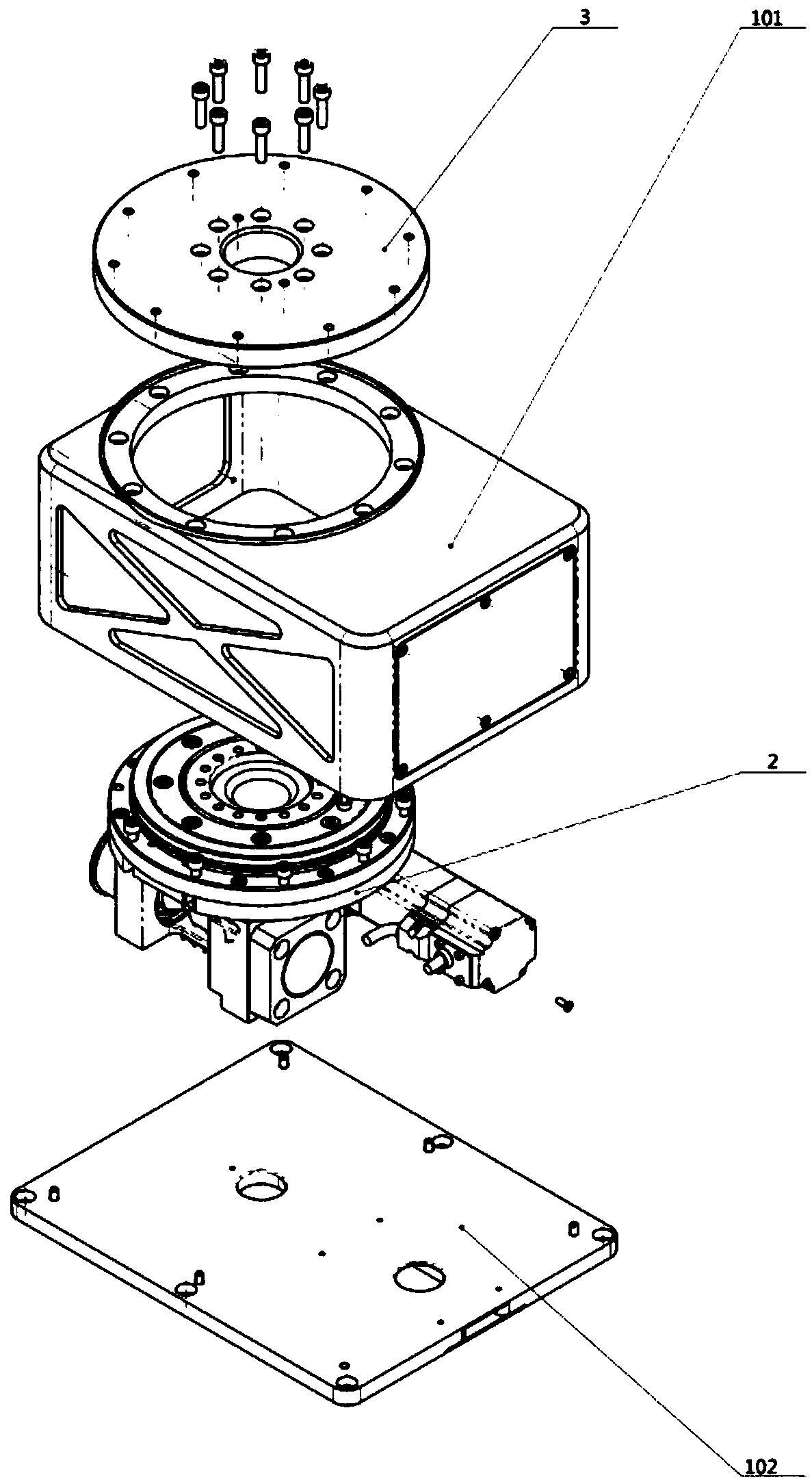
[0040] see figure 1 , the azimuth scanning and positioning mechanism provided in this embodiment is used in a radar system, and the azimuth scanning and positioning mechanism includes a housing 101, a flange 3 and a power module 2, wherein,

[0041] The inside of the housing 101 is hollow to accommodate the power module 2, and the housing 101 is a cuboid to maximize its fit with the overall shape of the power module 2, saving space; the flange 3 is circular, and the shell A circular first opening is opened on the top of the body, the flange is connected to the power module 2 through the first opening, and the flange 3 is placed on the first opening of the housing.

[0042] The azimuth scanning and positioning mechanism provided in this embodiment accommodates the power module in the casing 101, and the casing can be made of wear-resistant and anti-corrosion materials, which enhances the ability to prevent rain and dust, so as to protect the power module 2 inside the casing 101...

Embodiment 2

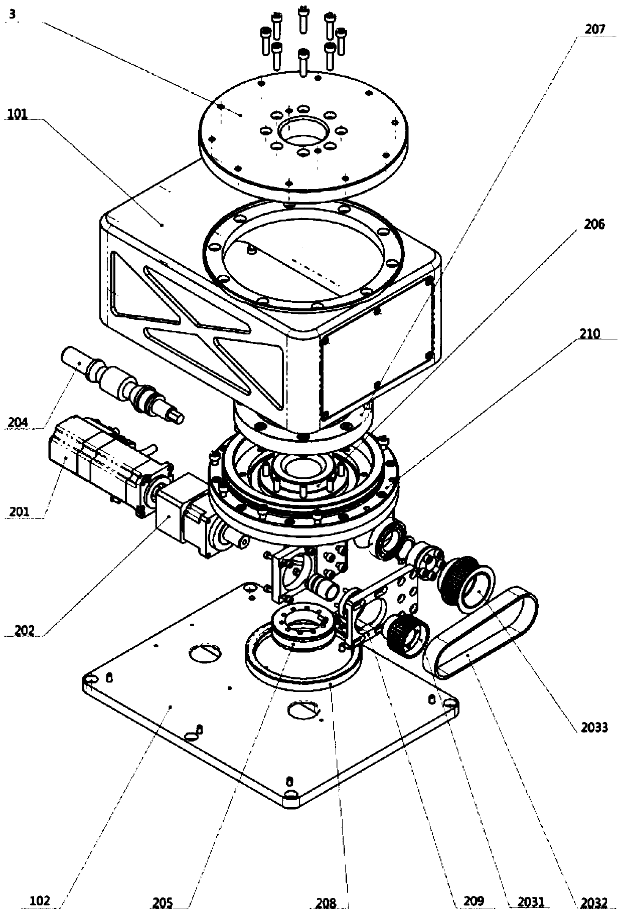
[0044] See figure 2 , image 3 or Figure 4 , the azimuth scanning positioning mechanism provided in this embodiment, the power module 2 includes a motor 201, a worm 204 and a synchronous belt module, the motor 201 and the worm 204 are arranged in parallel, and are respectively connected to the synchronous belt module, and the motor 201 rotates to drive the synchronous belt The module rotates, which in turn drives the worm to rotate.

[0045] Wherein, the synchronous belt module comprises a first synchronous pulley 2031, a second synchronous pulley 2033 and a synchronous belt 2032, the first synchronous pulley 2031 is fixedly connected on the rotating shaft of the motor 201, and the second synchronous pulley 2033 is fixed on the worm 204 On the rotating shaft of the second synchronous pulley 2033 and the rotating shaft of the worm screw 204, parts such as expansion sleeves, shaft retaining rings and bearings are added to reduce wear and make the connection more stable. The ...

Embodiment 3

[0050] See figure 2 , image 3 or Figure 4 In the azimuth scanning and positioning mechanism provided in this embodiment, the diameter of the flange 3 is greater than the diameter of the first opening at the top of the housing 101, and an upward annular protrusion is provided on the outside of the first opening, and the bottom of the flange 3 is provided with a The ring groove that the protrusion matches, the width and depth of the groove are slightly larger than the width and height of the protrusion on the housing 101, so as to avoid friction between the flange 3 and the housing 101 during the rotation process, and also avoid the Lan rotation torque is too large resulting in positional deviation.

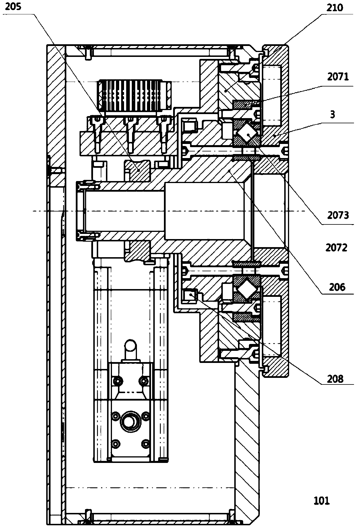
[0051] Please continue to see figure 2 , image 3 or Figure 4 In the azimuth scanning positioning mechanism provided in this embodiment, the power module 2 further includes a main shaft 206, a main shaft bearing 207 and an annular base 210, wherein the main shaft 206 is c...


PUM


Abstract

The invention discloses an azimuth scanning positioning mechanism and a radar system. The azimuth scanning positioning mechanism comprises a casing, a power module and a flange, wherein the power module is arranged inside the casing; a first opening is disposed at the top of the casing; the flange is disposed over the first opening and is connected with the power module through the first opening;and the power module rotates the flange so as to drive a radar fixed to the flange to rotate and scan. The radar system uses the azimuth scanning positioning mechanism. The flange connection manner increases the field angle of the radar and provides the radar with a larger field of view. In addition, the power module is housed in the casing so as to be compact in structure and easy to transport. The azimuth scanning positioning mechanism solves the defects that the azimuth scanning positioning mechanism of a conventional micro-change sensing early warning radar control system has a fixed fieldangle and a large size and is not easy to carry.

Description

technical field [0001] The invention relates to a slope radar system device, in particular to a compact azimuth scanning and positioning mechanism for a micro-variation sensing early warning radar. Background technique [0002] The micro-variation sensing radar system is mainly used in slope deformation monitoring technology. It has the technical advantages of non-contact, high-precision, large-area, all-weather, and 24-hour continuous monitoring. It is an important technical means for monitoring and early warning of collapse disasters. Reduce or avoid landslide disasters caused by slope displacement and deformation to the loss of life and property of the country and people. [0003] At present, in the typical systems at home and abroad, the accuracy of ground-based lidar to obtain terrain information is relatively high, but the accuracy in deformation monitoring is relatively low; the airborne lidar technology mentioned in "Study on Large-scale Artificial Slope Stability Gr...

Claims


Application Information

Patent Timeline
IPC IPC(8): G01B7/16G01S7/02
CPCG01B7/16G01S7/02G01S7/027
Inventor 王彦平林赟李洋张远田青
Owner NORTH CHINA UNIVERSITY OF TECHNOLOGY
Learn More