
Device and method for testing airflow distribution of dust remover

A technology of distributed testing and dust collectors, which is applied in measuring devices, fluid velocity measurement, full-field flow measurement, etc., can solve problems such as low safety and inaccurate data, and achieve the goal of avoiding injuries, ensuring personnel safety, and fast testing speed Effect

Active Publication Date: 2018-10-19
ANHUI CHENRUI ENERGY CONSERVATION & ENVIRONMENTAL PROTECTION SCI & ENG
View PDF10 Cites 1 Cited by
  • Summary
  • Abstract
  • Description
  • Claims
  • Application Information

AI Technical Summary

Problems solved by technology

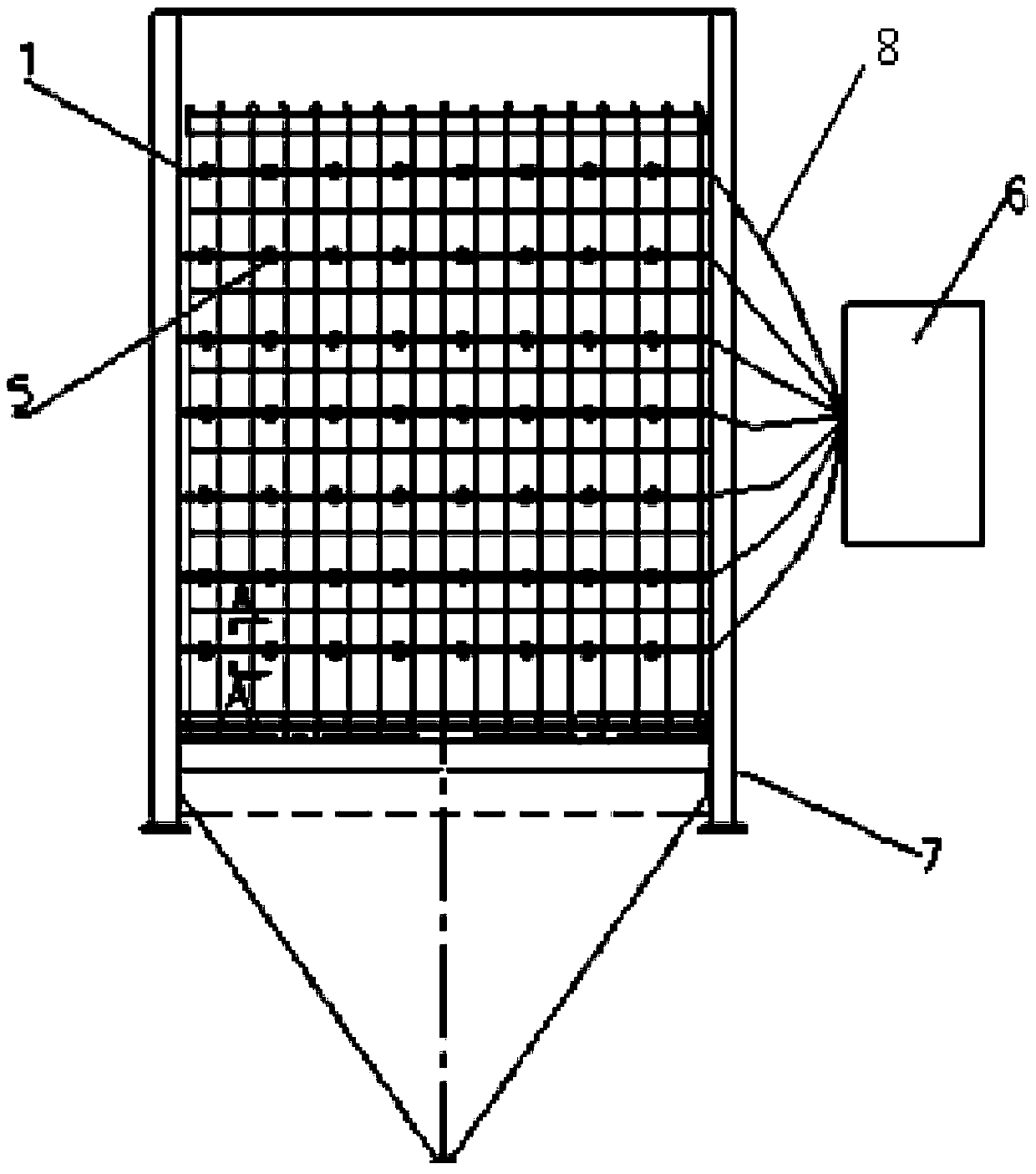
[0004] The purpose of the present invention is to solve the problems of low safety and inaccurate data existing in the airflow distribution test of the dust collector, and to provide a kind of airflow distribution test device for the dust collector, which is embedded in the steel pipe by using the steel pipe as the guide rail The test probe can effectively measure the wind speed of each point on the internal section of the dust collector, and the measured data is transmitted to the external controller through the cable, so that the mean square error of the airflow distribution can be automatically calculated, and the local or overall average wind speed can be displayed in real time

Method used


Image

  • Device and method for testing airflow distribution of dust remover
  • Device and method for testing airflow distribution of dust remover
  • Device and method for testing airflow distribution of dust remover

Examples


Embodiment Construction

[0021] In order to make the present invention clearer, the airflow distribution test device of the dust remover of the present invention will be further described below in conjunction with the accompanying drawings. The specific embodiments described here are only used to explain the present invention, not to limit the present invention.

[0022] like figure 1 Shown, a kind of airflow distribution testing device of dust collector, comprises dust collector 7, is characterized in that:

[0023] A group of steel pipes 1 arranged on the same vertical plane at the entrance of the dust collector 7, the number of steel pipes 1 in each group can be set to seven.

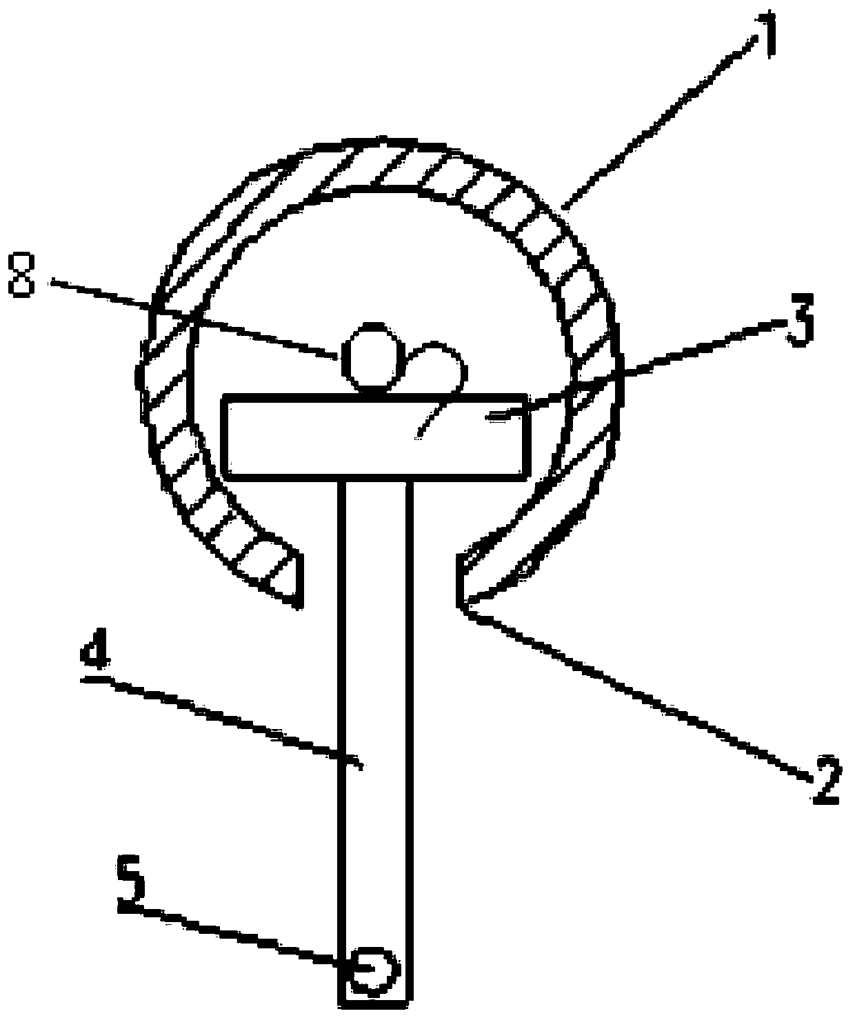
[0024] see figure 2 , Figure 4 , the outer wall of each steel pipe 1 is provided with an opening 2 along the generatrix, the length of the opening 2 is consistent with the length of the steel pipe 1, and the width of the opening 2 is smaller than the inner diameter of the steel pipe 1.

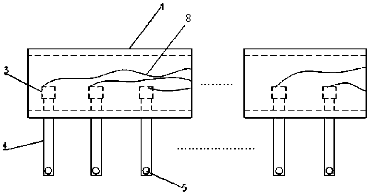
[0025] see figure 2 , image ...


PUM


Abstract

The invention relates to a method for testing the airflow distribution of a dust remover. The method is characterized by comprising selecting a test cross section of the dust remover and determining test points; installing steel pipes (1) according to the positions of the test points, wherein wind speed test probes are embedded in the steel pipes (1); adjusting the positions of the probes (5) in the steel pipes (1) so as to be consistent with the those of the test points; enabling a cable (8) connected to the probes (5) to extend out of the dust remover (7) from the steel pipes (1)in order tobe connected with a controller (6); turning on a fan and turning on an airflow distribution test device after the air volume and the air pressure of the fan are stabilized, transmitting the measured data to the controller (6) through the cable (8) so as to automatically calculate the mean square error of the airflow distribution and display the wind speed at each test point in real time. The method avoids the injury caused by the operation of a worker in the dust remover, is high in safety factor and easy and quick to operate, simultaneously measures multiple test points, can test the airflowdistribution in any partial range of a distribution point cross section, and improves the measurement efficiency and accuracy.

Description

technical field [0001] The invention relates to a test device, in particular to a test device and method for airflow distribution of a dust collector. Background technique [0002] In actual production, there are many factors that affect the purification efficiency of the dust collector, among which whether the air flow is evenly distributed in the dust collector has a great impact on the dust removal efficiency. When the airflow is evenly distributed, the dust collector can operate at its best; when the airflow is unevenly distributed, there is a big difference between the dust removal efficiency in the area with low flow velocity and the area with high flow velocity, and the total efficiency of dust removal will decrease, and the worse the airflow distribution will be. Uniformity, the lower the overall efficiency of dust removal. [0003] At present, in order to obtain a more accurate actual airflow distribution, the following two methods are usually adopted: first, the s...

Claims


Application Information

Patent Timeline
Patent Type & Authority Applications(China)
IPC IPC(8): G01P5/00
CPCG01P5/001
Inventor 宋锐管旭段磊邓浩宋昌贵王敏
Owner ANHUI CHENRUI ENERGY CONSERVATION & ENVIRONMENTAL PROTECTION SCI & ENG
Learn More